Multimedia ICs
BA3837 / BA3837F / BA3838F
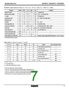
BA3838F (unless otherwise noted, Ta = 25°C, Vcc = 10V, fIN = 1kHz, VIN = 150mV, Rl = 100Ω)
Parameter
Quiescent current
Symbol
Min.
1.9
2.3
10
10
5
Typ.
2.7
2.8
14
14
8
Max.
3.6
—
17
Unit
mA
Vrms
dB
Conditions
I
Q
Through mode
THD 1%, through mode
Through mode
Maximum output voltage
L / R gain
Vom
=
G
G
VT
VF
Low frequency gain
Microphone gain
17
dB
fin
=
50kHz, vocal fader mode
G
VM
11
dB
—
Crosstalk
CT
SV
54
28
—
—
35
4.7
—
—
70
33
0.02
15
50
—
—
7
—
—
0.07
22
dB
f
IN
=
1kHz
Vocal suppression rate
Total harmonic distortion
Noise level
dB
Vocal fader mode
THD
%
Through mode, BW
:
400Hz - 30kHz
V
N
µ
Vrms
R
g
=
0, DIN AUDIO, through mode
Input impedance
Control pin threshold (high)
Control pin threshold (low)
Output switching DC differential
RIN
65
kΩ
LIN, RIN, MICIN, FK
VthH
VthL
—
0.3
46
V
V
—
—
∆
DC
mV
Maximum output voltage differential between L, R and TK modes
᭺
Not designed for radiation resistance.
Mode table (A = pin14, B = pin15, C = pin16)
A
0
0
0
0
1
1
1
1
B
0
0
1
1
0
0
1
1
C
0
1
0
1
0
1
0
1
LOUT
R
ROUT
R
TK
R
Mode
Key controller mode
Sound multiplexing mode (ROUT)
Vocal fader mode
—
—
—
—
VF
L
VF
L
VF
L
Sound multiplexing (LOUT)
Through mode
L
R
L
KC
KC
KC
KC
KC
KC
KC
KC
R
Sound multiplexing (R)
Vocal fader mode
•
•
•
•
VF
L
Sound multiplexing mode (L)
L + R
L + R
0
: 0V
1 : 5V
VF : vocal fader output
KC : signal passed through key controller
Gain and relative phase: See block diagram.
1. Gain of L / R input and output in the through mode: 14 dB (synchronous)
2. Gain of L / R input and TK output in the key controller mode: 8dB (synchronous)
3. Gain of FK input and L / R output in the key controller mode: 6dB (synchronous)
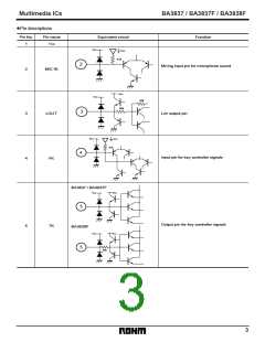
4. MIC input and L / R output are negative phase with a gain of 8dB.
7

 ROHM [ ROHM ]