Standaed ICs
BA15218 / BA15218F / BA15218N
80
32
28
24
20
16
12
8
100
75
60
40
20
50
25
4
0
– 20
100
1k
10k
100k
1M
0
20
40
60
80
0
10
20
30
40
FREQUENCY: f (Hz)
POWER SUPPLY VOLTAGE: V+ (V)
AMBIENT TEMPERATURE: Ta (°C)
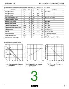
Fig.4 Maximum output voltage vs.
frequency
Fig.6 Input bias current vs.
power supply voltage
Fig.5 Input bias current vs.
ambient temperature
30
20
10
0
5
RL = 2kΩ
0
– 5
5
0
– 10
– 20
– 5
0
10
20
30
40
0
± 10
± 20
TIME (µs)
POWER SUPPLY VOLTAGE: V± (V)
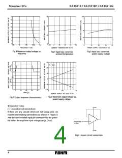
Fig.8 Maximum output voltage vs.
power supply voltage
Fig.7 Output response characteristics
Operation notes
•
VCC
(1) Unused circuit connections
If there are any circuits which are not being used, we
recommend making connections as shown in Figure 9,
with the non-inverted input pin connected to the poten-
tial within the in-phase input voltage range (VICM).
–
+
To potential
in VICM
VEE
Fig.9 Unused circuit connections
4

 ROHM [ ROHM ]