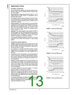
As shown, the Schottky diode is connected in parallel with
the internal parasitic diode and prevents it from being turned
on by limiting the voltage drop across it to about 0.3V.
Application Hints (Continued)
ON/OFF INPUT OPERATION
The LP2981 is shut off by pulling the ON/OFF input low, and
turned on by driving the input high. If this feature is not to be
used, the ON/OFF input should be tied to VIN to keep the
regulator on at all times (the ON/OFF input must not be left
floating).
To ensure proper operation, the signal source used to drive
the ON/OFF input must be able to swing above and below
the specified turn-on/turn-off voltage thresholds which guar-
antee an ON or OFF state (see Electrical Characteristics).
The ON/OFF signal may come from either a totem-pole
output, or an open-collector output with pull-up resistor to the
LP2981 input voltage or another logic supply. The high-level
voltage may exceed the LP2981 input voltage, but must
remain within the Absolute Maximum Ratings for the ON/
OFF pin.
01250642
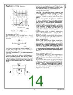
FIGURE 4. 3V/10 µF ESR Curves
REVERSE CURRENT PATH
It is also important that the turn-on/turn-off voltage signals
applied to the ON/OFF input have a slew rate which is
greater than 40 mV/µs.
Important: the regulator shutdown function will operate incor-
rectly if a slow-moving signal is applied to the ON/OFF input.
The power transistor used in the LP2981 has an inherent
diode connected between the regulator input and output
(see below).
MICRO SMD MOUNTING
The micro SMD package requires specific mounting tech-
niques which are detailed in National Semiconductor Appli-
cation Note # 1112. Referring to the section Surface Mount
Technology (SMT) Assembly Considerations, it should be
noted that the pad style which must be used with the 5-pin
package is the NSMD (non-solder mask defined) type.
01250641
For best results during assembly, alignment ordinals on the
PC board may be used to facilitate placement of the micro
SMD device.
If the output is forced above the input by more than a VBE
this diode will become forward biased and current will flow
from the VOUT terminal to VIN
,
.
<
This current must be limited to 100 mA to prevent damage
to the part.
MICRO SMD LIGHT SENSITIVITY
Exposing the micro SMD device to direct sunlight will cause
misoperation of the device. Light sources such as Halogen
lamps can also affect electrical performance if brought near
to the device.
The internal diode can also be turned on by abruptly step-
ping the input voltage to a value below the output voltage.
To prevent regulator mis-operation, a Schottky diode should
be used in any application where input/output voltage con-
ditions can cause the internal diode to be turned on (see
below).
The wavelenghts which have the most detrimental effect are
reds and infra-reds, which means that the fluorescent light-
ing used inside most buildings has very little effect on per-
formance. A micro SMD test board was brought to within 1
cm of a fluorescent desk lamp and the effect on the regu-
lated output voltage was negligible, showing a deviation of
less than 0.1% from nominal.
01250643
13
www.national.com

 ROCHESTER [ Rochester Electronics ]