Rx5C348A/B
ꢁ
Interrupt Process
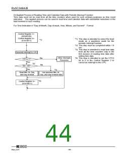
(1) Periodic Interrupt
Set Periodic Interrupt
Cycle Selection Bits
*1)
*1) This step is intended to select the level mode as a
waveform mode for the periodic interrupt function.
*2) This step is intended to set the CTFG bit to 0 in
the Control Register 2 to cancel an interrupt to the
CPU.
Generate Interrupt to CPU
No
Other Interrupt
Processes
CTFG=1?
Yes
Conduct
Periodic Interrupt
*2)
Control Register 2←
(X1X1X011)
(2) Alarm Interrupt
WALE or DALE←0
*1)
*1) This step is intended to once disable the alarm
interrupt circuit by setting the WALE or DALE bits to 0
in anticipation of the coincidental occurrence of a
match between current time and preset alarm time in
the process of setting the alarm interrupt function.
*2) This step is intended to enable the alarm interrupt
function after completion of all alarm interrupt
settings.
Set Alarm Min., Hr., and
Day-of-week Registers
*3) This step is intended to once cancel the alarm
interrupt function by writing the settings of "X,1,X,
1,X,1,0,1" and "X,1,X,1,X,1,1,0" to the Alarm_W
Registers and the Alarm_D Registers, respectively.
*2)
WALE or DALE←1
Generate Interrupt to CPU
No
Other Interrupt
Processes
WAFG or DAFG=1?
Yes
Conduct Alarm Interrupt
*3)
Control Register 2 ←
(X1X1X101)
12345
Rev.2.01
- 45 -

 RICOH [ RICOH ELECTRONICS DEVICES DIVISION ]