RT7274/79/80/81
changes, the switch voltage drops change causing a
switching frequency variation with load current. Also, at
light loads if the inductor current goes negative, the switch
dead-time between the synchronous rectifier turn-off and
the high-side switch turn-on allows the switching node to
rise to the input voltage. This increases the effective on-
time and causes the switching frequency to drop
noticeably.
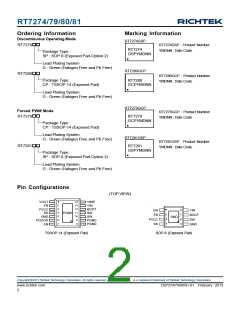
Discontinuous Operating Mode (RT7274/80 Only)
After soft start, the RT7279/81 operates in fixed frequency
mode to minimize interference and noise problems. The
RT7274/80 uses variable-frequency discontinuous
switching at light loads to improve efficiency. During
discontinuous switching, the on-time is immediately
increased to add “hysteresis” to discourage the IC from
switching back to continuous switching unless the load
increases substantially.
One way to reduce these effects is to measure the actual
switching frequency and compare it to the desired range.
This has the added benefit eliminating the need to sense
the actual output voltage, potentially saving one pin
connection. ACOTTM uses this method, measuring the
actual switching frequency and modifying the on-time with
a feedback loop to keep the average switching frequency
in the desired range.
The IC returns to continuous switching as soon as an on-
time is generated before the inductor current reaches zero.
The on-time is reduced back to the length needed for
700kHz switching and encouraging the circuit to remain
in continuous conduction, preventing repetitive mode
transitions between continuous switching and
discontinuous switching.
To achieve good stability with low-ESR ceramic capacitors,
ACOTTM uses a virtual inductor current ramp generated
inside the IC. This internal ramp signal replaces the ESR
ramp normally provided by the output capacitor's ESR.
The ramp signal and other internal compensations are
optimized for low-ESR ceramic output capacitors.
Current Limit
The RT7274/79/80/81 current limit is a cycle-by-cycle
“valley” type, measuring the inductor current through the
synchronous rectifier during the off-time while the inductor
current ramps down. The current is determined by
measuring the voltage between source and drain of the
synchronous rectifier, adding temperature compensation
for greater accuracy. If the current exceeds the upper
current limit, the on-time one-shot is inhibited until the
inductor current ramps down below the upper current limit
plus a wide hysteresis band of about 1Aand drops below
the lower current limit level. Thus, only when the inductor
current is well below the upper current limit is another on-
time permitted. This arrangement prevents the average
output current from greatly exceeding the guaranteed
upper current limit value, as typically occurs with other
valley-type current limits. If the output current exceeds
the available inductor current (controlled by the current
limit mechanism), the output voltage will drop. If it drops
below the output under-voltage protection level (see next
section) the IC will stop switching to avoid excessive heat.
ACOTTM One-shot Operation
The RT7274/79/80/81 control algorithm is simple to
understand. The feedback voltage, with the virtual inductor
current ramp added, is compared to the reference voltage.
When the combined signal is less than the reference the
on-time one-shot is triggered, as long as the minimum
off-time one-shot is clear and the measured inductor
current (through the synchronous rectifier) is below the
current limit. The on-time one-shot turns on the high-side
switch and the inductor current ramps up linearly. After
the on-time, the high-side switch is turned off and the
synchronous rectifier is turned on and the inductor current
ramps down linearly. At the same time, the minimum off-
time one-shot is triggered to prevent another immediate
on-time during the noisy switching time and allow the
feedback voltage and current sense signals to settle. The
minimum off-time is kept short (230ns typical) so that
rapidly-repeated on-times can raise the inductor current
quickly when needed.
The RT7279/81 also includes a negative current limit to
protect the IC against sinking excessive current and
possibly damaging the IC. If the voltage across the
synchronous rectifier indicates the negative current is too
Copyright 2013 Richtek Technology Corporation. All rights reserved.
©
is a registered trademark of Richtek Technology Corporation.
www.richtek.com
6
DS7274/79/80/81-01 February 2013

 RICHTEK [ RICHTEK TECHNOLOGY CORPORATION ]