RT7272B
Layout Considerations
For best performance of the RT7272B, the following layout
guidelines must be strictly followed.
Input capacitor must be placed as close to the IC as
possible.
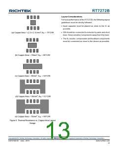
(a) Copper Area = (2.3 x 2.3) mm2,θJA = 75°C/W
SW should be connected to inductor by wide and short
trace. Keep sensitive components away from this trace.
The RL resistor, compensator and feedback components
must be connected as close to the device as possible.
(b) Copper Area = 10mm2,θJA = 64°C/W
(c) Copper Area = 30mm2 , θJA = 54°C/W
(d) Copper Area = 50mm2 ,θJA = 51°C/W
(e) Copper Area = 70mm2 ,θJA = 49°C/W
Figure 6. Thermal Resistance vs. CopperArea Layout
Design
Copyright 2015 Richtek Technology Corporation. All rights reserved.
©
is a registered trademark of Richtek Technology Corporation.
DS7272B-05 June 2015
www.richtek.com
13

 RICHTEK [ RICHTEK TECHNOLOGY CORPORATION ]