X9313
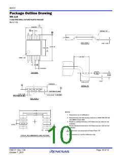
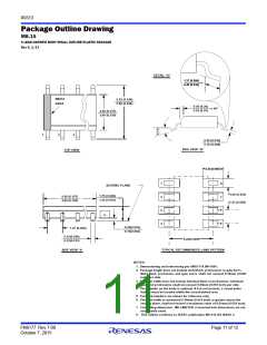
Package Outline Drawing
M8.118
8 LEAD MINI SMALL OUTLINE PLASTIC PACKAGE
Rev 4, 7/11
5
3.0±0.05
A
DETAIL "X"
D
8
1.10 MAX
SIDE VIEW 2
0.09 - 0.20
4.9±0.15
3.0±0.05
5
0.95 REF
PIN# 1 ID
1
2
B
0.65 BSC
GAUGE
PLANE
TOP VIEW
0.25
3°±3°
0.55 ± 0.15
DETAIL "X"
0.85±010
H
C
SEATING PLANE
0.10 C
0.25 - 0.36
0.10 ± 0.05
0.08
C A-B D
M
SIDE VIEW 1
(5.80)
NOTES:
1. Dimensions are in millimeters.
(4.40)
(3.00)
2. Dimensioning and tolerancing conform to JEDEC MO-187-AA
and AMSEY14.5m-1994.
3. Plastic or metal protrusions of 0.15mm max per side are not
included.
(0.65)
4. Plastic interlead protrusions of 0.15mm max per side are not
included.
(0.40)
(1.40)
5. Dimensions are measured at Datum Plane "H".
6. Dimensions in ( ) are for reference only.
TYPICAL RECOMMENDED LAND PATTERN
FN8177 Rev 7.00
October 7, 2015
Page 10 of 12

 RENESAS [ RENESAS TECHNOLOGY CORP ]