RX62N Group, RX621 Group
1. Overview
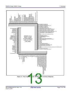
1.3
Block Diagram
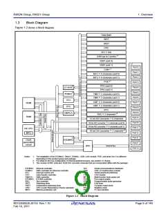
Figure 1.2 shows a block diagram.
Data flash
WDT
IWDT
CRC
SCI × 6ch
USB (up to 2 ports)
RSPI (unit 0)
RSPI (unit 1)
CAN *1
1
*
1
*
Port 0
Port 1
Port 2
Port 3
Port 4
Port 5
Port 6
Port 7
Port 8
Port 9
MTU × 6 channels (unit 0)
MTU × 6 channels (unit 1)
1
*
POE
1
PPG (unit 0)
PPG (unit 1)
*
ETHERC
1
*
EDMAC
TMR × 2 channels (unit 0)
TMR × 2 channels (unit 1)
ICU
DTC
CMT × 2 channels (unit 0)
CMT × 2 channels (unit 1)
ROM
RAM
RTC
DMACA
3
*
RIIC × 2 channels
Port A
Port B
Port C
Port D
Port E
Port F
Port G
12-bit A/D converter × 8 channels
10-bit A/D converter × 4 channels (unit 0)
10-bit A/D converter × 4 channels (unit 1)
RX CPU
MPU
3
*
10-bit D/A converter × 2 channels
1
*
Clock
generation
circuit
EXDMAC
External bus
BSC
Notes: 1. The installation of the EXDMAC, EtherC, EDMAC, USB, CAN module, POE, and ports 0 to G is different
depending on the product group and package.
2. For detail on the bus configuration of internal peripheral buses, see section 12, Buses.
3. The number of RIIC units and 10-bit D/A converter channels that are incorporated differs with the package.
ETHERC: Ethernet controller
SCI:
Serial communications interfaces
USB 2.0 host/function module
Serial peripheral interfaces
CAN module
Multi-function timer pulse unit
Port output enable
EDMAC:
ICU:
DTC:
DMA controller for Ethernet controller
USB:
RSPI:
CAN:
MTU:
POE:
PPG:
TMR:
CMT:
RTC:
RIIC:
Interrupt control unit
Data transfer controller
DMA controller
DMACA:
EXDMAC: EXDMA controller
BSC:
WDT:
IWDT:
CRC:
MPU:
Bus controller
Watchdog timer
Independent watchdog timer
CRC (Cyclic Redundancy Check) calculator
Memory-protection unit
Programmable pulse generator
8-bit timer
Compare match timer
Realtime clock
I2C bus interface
Figure 1.2 Block Diagram
R01DS0052EJ0110 Rev.1.10
Feb 10, 2011
Page 9 of 146

 RENESAS [ RENESAS TECHNOLOGY CORP ]