MITSUBISHI MICROCOMPUTERS
M37270MF-XXXSP
M37270EF-XXXSP, M37270EFSP
SINGLE-CHIP 8-BIT CMOS MICROCOMPUTER with CLOSED CAPTION DECODER
and ON-SCREEN DISPLAY CONTROLLER
7 of the block control register (refer to Figure 50). The setting values
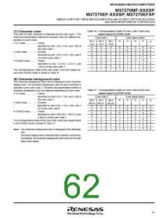
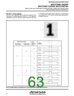
(9) OUT1, OUT2 signals
The OUT1, OUT2 signals are used to control the luminance of the
video signal. The output waveform of the OUT1, OUT2 signals is
controlled by bit 4 of the color code 1 (refer to Figure 65), bits 2 and
for controlling OUT1, OUT2 and the corresponding output waveform
is shown in Figure 66.
Block control register
OUT1
control
(b4 of color
code 1)
Output
waveform
OUT2 output
control bit (b7)
Border output
control bit (b2)
OUT1
OUT2
0
1
0
1
0
1
0
1
OUT1
OUT2
0
OUT1
OUT2
OUT1
OUT2
OUT1
OUT2
0
1
OUT1
OUT2
1
OUT1
OUT2
0
1
OUT1
OUT2
Fig. 66. Setting value for controlling OUT1, OUT2 and corresponding output waveform
62

 RENESAS [ RENESAS TECHNOLOGY CORP ]