M37161M8/MA/MF-XXXSP/FP,M37161EFSP/FP
8.10.12 Scan mode
The Bi-scan mode corresponds to HSYNC of twice as much frequency
as usual. The vertical display position and the vertical dot size double
compared to the normal scan mode. Scan mode can be set the ver-
tical dot size in bit 0 of OSD control register 2, and the vertical dis-
play start position in bit 1, independently .
Table 8.10.3 Setting of Scan Mode
Scan mode
Normal scan
Bi-scan
1
Item
0
Bit 0 of OSD control register 2
Vertical dot size
1T
1T
2T
3T
C✕✕ 1/2H
C✕✕ 1H
C✕✕ 2H
C✕✕ 3H
0
1T
1T
2T
3T
C✕✕ 1H
C✕✕ 2H
C✕✕ 4H
C✕✕ 6H
1
Bit 1 of OSD control register 2
Verical display start position
A value of verical position register ✕ 1H
A value of verical position register ✕ 2H
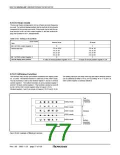
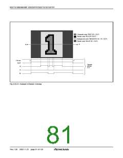
8.10.13 Window Function
This function sets the top and bottom boundaries for display limits
on a screen. The window function is valid only in the OSD1 mode.
The top boundary is set by the window register 1 and bit 7 of block
control register 1. The bottom boundary is set by window register 1
and bit 7 of block control register 2. This function is turned on and off
by bit 2 of the OSD control register (refer to Figure 8.10.3).
The setting value per one step of the top and bottom window borders
can be switched to either 1TH or 2TH by setting “0” or “1” to bit 1 of
OSD control register 2 (address 02DB16).
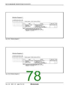
Window registers 1 and 2 are shown in Figures 8.10.27 and 8.10.28.
Top
boundary
of window
OSD2 mode
OSD1 mode
A B C D E
F G H
I
J
OSD1 mode
OSD1 mode
K L M N O
Window
P Q R S T
U V W X Y
OSD2 mode
Bottom
boundary
of window
Screen
Fig. 8.10.26 Example of Window Function
Rev.1.00 2003.11.25 page 77 of 128

 RENESAS [ RENESAS TECHNOLOGY CORP ]