M37161M8/MA/MF-XXXSP/FP,M37161EFSP/FP
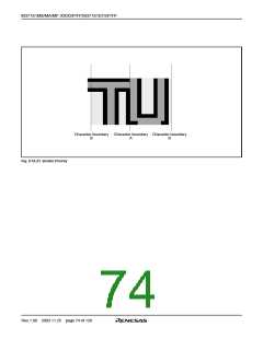
Notes 1 : The border dot area is the shaded area as shown in Figure 8.10.21.
2 : When the border dot overlaps on the next character font, the charac-
ter font has priority (refer to Figure 8.10.23 A).
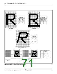
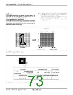
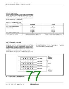
(4) Border
The border is output around the character font (all bordered) in the
OSD2 mode only. The border ON/OFF is controlled by bit 0 and 1 of
block control register i (refer to Figure 8.10.4).
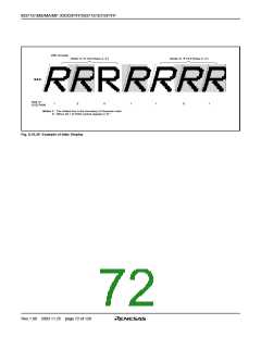
When the border dot overlaps the next character back ground, the
border has priority (refer to Figure 8.10.23 B).
3 : The border in vertical out of the character area is not displayed (refer
to Figure 8.10.23).
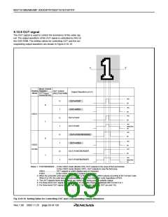
The OUT signal is used for border output.
The horizontal size (x) of the border is 1TC (OSD clock cycle divided
in pre-divide circuit) regardless of the character font dot size. The
vertical size (y) differs depending on the screen scan mode and the
vertical dot size of the character font.
OSD2 mode
16 dots
Character
font area
All bordered
1 dot width of border
1 dot width of border
Fig. 8.10.21 Example of Border Display
y
x
Scan mode
Normal scan mode
1/2H
Bi-scan mode
Vertical dot size of
character font
1H, 2H, 4H, 6H
1H, 2H, 3H
Border dot size
1Tc (OSD clock cycle divided in pre-divide circuit)
1/2H
Horizontal size (x)
Vertical size (y)
1H
1H
Fig. 8.10.22 Horizontal and Vertical Size of Border
Rev.1.00 2003.11.25 page 73 of 128

 RENESAS [ RENESAS TECHNOLOGY CORP ]