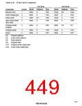
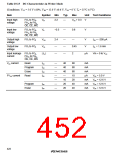
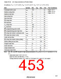
Table 19.16 AC Characteristics in Writer Mode
(Conditions: VCC = 5.0 V ±10%, VPP = 12.0 V ±0.6 V, VSS = 0 V, Ta = 25°C ±5°C)
Item
Symbol Min
Typ
—
—
—
—
—
—
—
—
—
—
—
—
—
—
—
—
—
—
—
—
Max Unit Test Conditions
Command write cycle
Address setup time
Address hold time
Data setup time
tCWC
tAS
120
0
—
—
—
—
—
—
—
—
—
—
—
—
—
500
—
120
—
11
40
30
ns
ns
ns
ns
ns
ns
ns
ns
ns
ns
ns
ns
µs
ns
ns
ns
ns
ms
ns
s
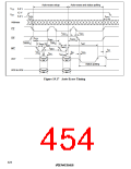
Figure 19.17
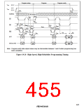
Figure 19.18*
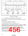
Figure 19.19
tAH
60
50
10
0
tDS
Data hold time
tDH
CE setup time
tCES
tCEH
tVPS
tVPH
tWEP
tWEH
CE hold time
0
VPP setup time
100
100
70
40
0
VPP hold time
WE programming pulse width
WE programming pulse high time
OE setup time before command write tOEWS
OE setup time before verify
Verify access time
tOERS
tVA
6
—
120
—
25
9
OE setup time before status polling
Status polling access time
Program wait time
tOEPS
tSPA
tPPW
tET
Erase wait time
Output disable time
tDF
0
Total auto-erase time
tAET
0.5
Note: CE, OE, and WE should be high during transitions of VPP from 5 V to 12 V and from 12 V to
5 V.
* Input pulse level: 0.45 V to 2.4 V
Input rise time and fall time ≤ 10 ns
Timing reference levels: 0.8 V and 2.0 V for input; 0.8 V and 2.0 V for output
423

 RENESAS [ RENESAS TECHNOLOGY CORP ]