14.2.9
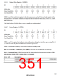
Serial/Timer Control Register (STCR)
Bit
7
6
5
4
3
STAC
0
2
1
ICKS1
0
0
ICKS0
0
IICS
0
IICD
0
IICX
0
IICE
0
MPE
0
Initial value
Read/Write
R/W
R/W
R/W
R/W
R/W
R/W
R/W
R/W
STCR is an 8-bit readable/writable register that controls the I2C bus interface and host interface
and the SCI operating mode, and selects the TCNT clock source. STCR is initialized to H'00 by a
reset and in hardware standby mode.
Bits 7 to 4—I2C Control (IICS, IICD, IICX, IICE): These bits are used to control the I2C bus
interface. For details, see section 13, I2C Bus Interface.
Bit 3—Slave Input Switch (STAC): Controls switching of host interface input pins. Settings of
this bit are valid only when the host interface is enabled (slave mode).
Bit 3: STAC
Description
0
1
In port 8, P85 switches over to CS2, and P84 to IOW
In port 9, P91 switches over to EIOW, and P90 to ECS2
(Initial value)
Bit 2—Multiprocessor Enable (MPE): Controls the operating mode of SCI0 and SCI1. For
details, see section 12, Serial Communication Interface.
Bits 1 and 0—Internal Clock Source Select 1 and 0 (ICKS1, ICSK0): Together with bits CKS2
to CKS0 in TCR, these bits select timer counter clock inputs. For details, see section 9, 8-Bit
Timers.
325

 RENESAS [ RENESAS TECHNOLOGY CORP ]