10.1.4
Register Configuration
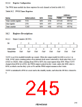
The PWM timer module has three registers for each channel as listed in table 10.2.
Table 10.2 PWM Timer Registers
Address
Initial
Value
Name
Abbreviation
TCR
R/W
R/W
R/W
R/W
PWM0
H'FFA0
H'FFA1
H'FFA2
PWM1
H'FFA4
H'FFA5
H'FFA6
Timer control register
Duty register
Timer counter
H'38
H'FF
H'00
DTR
TCNT
10.2
Register Descriptions
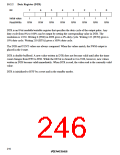
10.2.1
Timer Counter (TCNT)
Bit
7
6
5
4
0
3
2
1
0
0
Initial value
Read/Write
0
0
0
0
0
0
R/W
R/W
R/W
R/W
R/W
R/W
R/W
R/W
TCNT is an 8-bit readable/writable up-counter. When the output enable bit (OE) is set to 1 in
TCR, TCNT starts counting pulses of an internal clock source selected by clock select bits 2 to 0
(CKS2 to CKS0). After counting from H'00 to H'F9, the count repeats from H'00. When TCNT
changes from H'00 to to H'01, the PWM output is placed in the 1 state, unless the DTR value is
H'00, in which case the duty cycle is 0% and the PWM output remains in the 0 state.
TCNT is initialized to H'00 at a reset and in the standby modes, and when the OE bit is cleared to
0.
215

 RENESAS [ RENESAS TECHNOLOGY CORP ]