9.1.3
Input and Output Pins
Table 9.1 lists the input and output pins of the 8-bit timer.
Table 9.1 Input and Output Pins of 8-Bit Timer
Abbreviation*
Name
Channel 0
TMO0
Channel 1
TMO1
I/O
Function
Timer output
Timer clock input
Timer reset input
Output
Input
Input
Output controlled by compare-match
External clock source for the counter
External reset signal for the counter
TMCI0
TMCI1
TMRI0
TMRI1
Note: * In this manual, the channel subscript has been deleted, and only TMO, TMCI, and TMRI
are used.
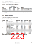
9.1.4
Register Configuration
Table 9.2 lists the registers of the 8-bit timer module.
Table 9.2 8-Bit Timer Registers
Channel
Name
Abbreviation R/W
Initial Value Address
0
Timer control register
Timer control/status register
Time constant register A
Time constant register B
Timer counter
TCR
R/W
H'00
H'FFC8
H'FFC9
H'FFCA
H'FFCB
H'FFCC
H'FFD0
H'FFD1
H'FFD2
H'FFD3
H'FFD4
H'FFC3
TCSR
TCORA
TCORB
TCNT
TCR
R/(W)* H'10
R/W
R/W
R/W
R/W
H'FF
H'FF
H'00
H'00
1
Timer control register
Timer control/status register
Time constant register A
Time constant register B
Timer counter
TCSR
TCORA
TCORB
TCNT
STCR
R/(W)* H'10
R/W
R/W
R/W
R/W
H'FF
H'FF
H'00
H'00
0, 1
Serial/timer control register
Note: * Software can write a 0 to clear bits 7 to 5, but cannot write a 1 in these bits.
193

 RENESAS [ RENESAS TECHNOLOGY CORP ]