Appendix
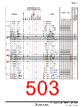
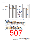
8. Block Transfer Instructions
Addressing Mode and
Instruction Length (bytes)
No. of
States*1
Condition Code
Mnemonic
Operation
I
H
N
Z
V
C
EEPMOV
EEPMOV. B
—
—
4
4
if R4L ≠ 0 then
repeat @R5 → @R6
R5+1 → R5
—
—
—
—
—
—
8+
4n*2
R6+1 → R6
R4L–1 → R4L
until
else next
R4L=0
EEPMOV. W
if R4 ≠ 0 then
repeat @R5 → @R6
R5+1 → R5
—
—
—
—
—
—
8+
4n*2
R6+1 → R6
R4–1 → R4
until
R4=0
else next
Notes: 1. The number of states in cases where the instruction code and its operands are located
in on-chip memory is shown here. For other cases see appendix A.3, Number of
Execution States.
2. n is the value set in register R4L or R4.
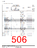
(1) Set to 1 when a carry or borrow occurs at bit 11; otherwise cleared to 0.
(2) Set to 1 when a carry or borrow occurs at bit 27; otherwise cleared to 0.
(3) Retains its previous value when the result is zero; otherwise cleared to 0.
(4) Set to 1 when the adjustment produces a carry; otherwise retains its previous value.
(5) The number of states required for execution of an instruction that transfers data in
synchronization with the E clock is variable.
(6) Set to 1 when the divisor is negative; otherwise cleared to 0.
(7) Set to 1 when the divisor is zero; otherwise cleared to 0.
(8) Set to 1 when the quotient is negative; otherwise cleared to 0.
Rev. 3.00 Sep. 10, 2007 Page 473 of 528
REJ09B0216-0300

 RENESAS [ RENESAS TECHNOLOGY CORP ]