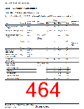
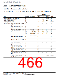
Section 22 Electrical Characteristics
22.2.7
Power-Supply-Voltage Detection Circuit Characteristics
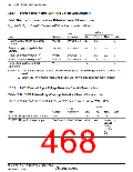
Table 22.9 Power-Supply-Voltage Detection Circuit Characteristics
VSS = 0.0 V, Ta = -20 to +75°C/-40 to +85°C, unless otherwise indicated.
Values
Typ.
Test
Condition
Item
Symbol
Min.
Max.
Unit
Power-supply falling detection
voltage
Vint (D)
LVDSEL = 0
3.4
3.7
—
V
Power-supply rising detection
voltage
Vint (U)
LVDSEL = 0
—
4.0
4.4
V
Reset detection voltage 1*1
Reset detection voltage 2*2
Vreset1
Vreset2
VLVDRmin
LVDSEL = 0
LVDSEL = 1
—
2.3
3.6
—
2.6
3.9
—
V
V
V
3.3
1.0
Lower-limit voltage of LVDR
operation
Notes: 1. This voltage should be used when the falling and rising voltage detection function is
used.
2. Select the low-voltage reset 2 when only the low-voltage detection reset is used.
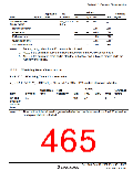
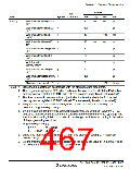
22.2.8
LVDI External Input Voltage Detection Circuit Characteristics
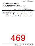
Table 22.10 LVDI External Input Voltage Detection Circuit Characteristics
Vcc = 4.5 to 5.5 V, AVcc = 4.5 to 5.5 V, VSS = 0.0 V, Ta = -20 to +75°C/-40 to +85°C
Values
Test
Item
Symbol
Condition
Min.
Typ.
1.15
Max.
Unit
V
ExtD/ExtU input detection voltage
ExtD/ExtU input voltage range
Vexd
1.0
1.30
VextD/VextU VextD > VextU −0.3
Lower
V
voltage
of AVcc
+ 0.3 or
Vcc
+
0.3
Rev. 3.00 Sep. 10, 2007 Page 434 of 528
REJ09B0216-0300

 RENESAS [ RENESAS TECHNOLOGY CORP ]