11.1.3 Pin Configuration
Table 11.1 shows the RTC pins.
Table 11.1 RTC Pins
Pin Name
Abbreviation
I/O
Function
RTC oscillator crystal pin
RTC oscillator crystal pin
Clock input/clock output
EXTAL2
XTAL2
TCLK
Input
Output
I/O
Connects crystal to RTC oscillator
Connects crystal to RTC oscillator
External clock input pin/input capture
control input pin/RTC output pin
(shared with TMU)
Dedicated RTC power
supply
VDD-RTC
VSS-RTC
—
—
RTC oscillator power supply pin*
Dedicated RTC GND pin
RTC oscillator GND pin*
Note: * Power must be supplied to the RTC power supply pins even when the RTC is not used.
11.1.4 Register Configuration
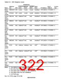
Table 11.2 summarizes the RTC registers.
Table 11.2 RTC Registers
Initialization
Power-
Abbrevia-
tion
On
Manual Standby Initial
Reset Mode Value
Area 7
P4 Address Address
Access
Size
Name
R/W Reset
64 Hz
counter
R64CNT
R
Counts Counts Counts Undefined H'FFC80000 H'1FC80000
8
8
8
8
8
Second
counter
RSECCNT R/W Counts Counts Counts Undefined H'FFC80004 H'1FC80004
RMINCNT R/W Counts Counts Counts Undefined H'FFC80008 H'1FC80008
Minute
counter
Hour
counter
RHRCNT
R/W Counts Counts Counts Undefined H'FFC8000C H'1FC8000C
Day-of-
week
counter
RWKCNT R/W Counts Counts Counts Undefined H'FFC80010 H'1FC80010
RDAYCNT R/W Counts Counts Counts Undefined H'FFC80014 H'1FC80014
Day
8
counter
Rev. 6.0, 07/02, page 269 of 986

 RENESAS [ RENESAS TECHNOLOGY CORP ]