INTERRUPTS
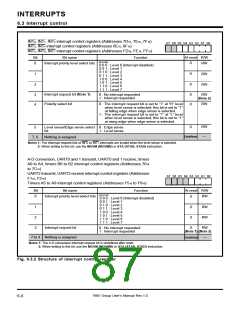
6.3 Interrupt control
INT
INT
INT
0
3
5
, INT
, INT
, INT
1
4
6
, INT
interrupt control registers (Addresses 6E16, 6F16
, INT interrupt control registers (Addresses FD16, FE16, FF16
Bit name
Function
2
interrupt control registers (Addresses 7D16, 7E16, 7F16)
b7 b6 b5 b4 b3 b2 b1 b0
At reset R/W
)
7
)
Bit
0
b2 b1b0
0
0
0
Interrupt priority level select bits
RW
RW
RW
0 0 0 : Level 0 (Interrupt disabled)
0 0 1 : Level 1
0 1 0 : Level 2
0 1 1 : Level 3
1
2
1 0 0 : Level 4
1 0 1 : Level 5
1 1 0 : Level 6
1 1 1 : Level 7
Interrupt request bit (Note 1)
RW
(Note 2)
0 : No interrupt requested
1 : Interrupt requested
0
0
3
4
Polarity select bit
0 : The interrupt request bit is set to “1” at “H” level
when level sense is selected; this bit is set to “1”
at falling edge when edge sense is selected.
1 : The interrupt request bit is set to “1” at “L” level
when level sense is selected; this bit is set to “1”
at rising edge when edge sense is selected.
RW
RW
0
5
Level sense/Edge sense select 0 : Edge sense
bit
1 : Level sense
Undefined
—
Nothing is assigned.
7, 6
Notes 1: The interrupt request bits of INT0 to INT7 interrupts are invalid when the level sense is selected.
2: When writing to this bit, use the MOVM (MOVMB) or STA (STAB, STAD) instruction.
A-D conversion, UART0 and 1 transmit, UART0 and 1 receive, timers
A0 to A4, timers B0 to B2 interrupt control registers (Addresses 7016
to 7C16)
UART2 transmit, UART2 receive interrupt control registers (Addresses
F116, F216)
Timers A5 to A9 interrupt control registers (Addresses F516 to F916)
b7 b6 b5 b4 b3 b2 b1 b0
At reset R/W
Bit
0
Bit name
Function
b2 b1b0
Interrupt priority level select bits
0
0
0
0
RW
RW
RW
RW
0 0 0 : Level 0 (Interrupt disabled)
0 0 1 : Level 1
0 1 0 : Level 2
1
2
3
0 1 1 : Level 3
1 0 0 : Level 4
1 0 1 : Level 5
1 1 0 : Level 6
1 1 1 : Level 7
Interrupt request bit
0 : No interrupt requested
1 : Interrupt requested
(Note 1) (Note 2)
7 to 4 Nothing is assigned.
Undefined
—
Notes 1: The A-D conversion interrupt request bit is undefined after reset.
2: When writing to this bit, use the MOVM (MOVMB) or STA (STAB, STAD) instruction.
Fig. 6.3.2 Structure of interrupt control register
7905 Group User’s Manual Rev.1.0
6-6

 RENESAS [ RENESAS TECHNOLOGY CORP ]