RESET
3.1 Reset operation
There are 3 ways to reset the microcomputer:
Hardware reset : Apply “L” level of voltage to pin RESET while the power source voltage (Vcc) meets
the recommended operating conditions.
Software reset : Write “1” to the software reset bit (bit 6 at address 5E16) while the power source
voltage (Vcc) meets the recommended operating conditions.
Power-on reset : After power-on, raise the voltage level at pin Vcc to the level, which meets the
recommend operating conditions, with “L” level of voltage applied to pin RESET.
3.1 Reset operation
Operations of hardware, software, and power-on reset are described below.
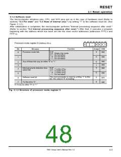
3.1.1 Hardware reset
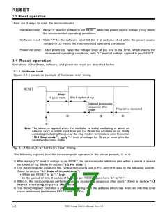
Figure 3.1.1 shows an example of hardware reset timing.
RESET
(Note)
10 µs or more
8 to 9 cycles of fsys
Internal processing
sequence after
reset
Program is executed.
➀
➀
➀
➀
Note: The above is applied when the oscillator is stably oscillating or when an
external clock is stably input from pin XIN. When the oscillator is not stably
oscillating (including the case at the stop mode’s termination; refer to section
“15.3 Stop mode.”), apply “L” level of voltage for 10 µs or more after the
oscillation becomes stable.
Fig. 3.1.1 Example of hardware reset timing
The following explains how the microcomputer operates in the above periods, ➀ to ➀.
➀ After applying “L” level of voltage to pin RESET, the microcomputer initializes pins within a period of several
ten cycles of fsys. (Refer to section “3.2 Pin state.”)
➀ The microcomputer initializes the central processing unit (CPU) and SFR area in the following periods.
(Refer to section “3.3 State of internal area.”)
• While pin RESET is at “L” level.
• In the period of 8 to 9 cycles of fsys after pin RESET goes from “L” to “H.”
➀ After ➀, the microcomputer performs “Internal processing sequence after reset.” (Refer to section “3.4
Internal processing sequence after reset.”)
➀ The microcomputer executes a program beginning with the address which has been set into the reset
vector addresses (addresses FFFE16 and FFFF16).
7905 Group User’s Manual Rev.1.0
3-2

 RENESAS [ RENESAS TECHNOLOGY CORP ]