APPENDIX
Appendix 2. Control registers
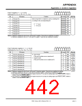
UART0 transmit/receive mode register (Address 3016
UART1 transmit/receive mode register (Address 3816
)
)
b7 b6 b5 b4 b3 b2 b1 b0
UART2 transmit/receive mode register (Address B016
)
Function
0 0 0 : Serial I/O is invalid.
Reference
Bit
0
Bit name
At reset R/W
b2 b1b0
0
0
0
RW
RW
RW
Serial I/O mode select bits
11-5
(P1 and P8 function as programmable I/O ports.)
0 0 1 : Clock synchronous serial I/O mode
1
2
0 1 0 :
0 1 1 :
Do not select.
1 0 0 : UART mode (Transfer data length = 7 bits)
1 0 1 : UART mode (Transfer data length = 8 bits)
1 1 0 : UART mode (Transfer data length = 9 bits)
1 1 1 : Do not select.
Internal/External clock select bit
Stop bit length select bit
0 : Internal clock
1 : External clock
3
4
5
0
0
0
RW
RW
RW
0 : One stop bit
1 : Two stop bits
(Valid in UART mode)
(Note)
Odd/Even parity select bit
(Valid in UART mode when parity
0 : Odd parity
1 : Even parity
enable bit = “1.”)
(Note)
Parity enable bit
(Valid in UART mode)
0 : Parity disabled
1 : Parity enabled
6
7
0
0
RW
RW
(Note)
Sleep select bit
(Valid in UART mode)
0 : Sleep mode terminated (Invalid)
1 : Sleep mode selected
(Note)
Note: Bits 4 to 6 are invalid in the clock synchronous serial I/O mode. (Each may be either “0” or “1.”) Additionally, fix bit 7 to “0.”
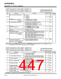
UART0 baud rate register (BRG0) (Address 3116
UART1 baud rate register (BRG1) (Address 3916
)
)
b7
b0
UART2 baud rate register (BRG2) (Address B116
)
Reference
Function
Bit
At reset R/W
Any value in the range from “0016” to “FF16” can be set.
Assuming that the set value = n, BRGi divides the count source frequency by (n + 1).
Undefined WO
11-14
7 to 0
Note: Writing to this register must be performed while the transmission/reception halts.
Use the MOVM (MOVMB) or STA (STAB, STAD) instruction for writing to this register.
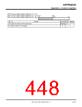
UART0 transmit buffer register (Addresses 3316, 3216
UART1 transmit buffer register (Addresses 3B16, 3A
UART2 transmit buffer register (Addresses B316, B216
)
(b8)
b0 b7
16 (b15)
)
b7
b0
)
Function
Bit
At reset R/W
Undefined WO
Reference
8 to 0 Transmit data is set.
15 to 9 Nothing is assigned.
11-11
Undefined
–
Note: Use the MOVM (MOVMB) or STA (STAB, STAD) instruction for writing to this register.
7905 Group User’s Manual Rev.1.0
20-15

 RENESAS [ RENESAS TECHNOLOGY CORP ]