APPLICATIONS
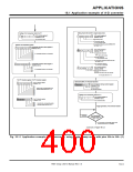
18.1 Application example of A-D converter
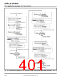
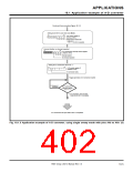
Continued from preceding Figure 18.1.2.
Setting of pin AN11 to one-shot mode (Note)
b7
b0
A-D control register 2
(Address DB16
0
0
0
0
1
0
1
1
)
Analog input pin select bits 1
b3 b2 b1 b0
1
0 1 1: Pin AN11 is selected.
Interrupt disabled, no interrupt requested
b7
b0
A-D conversion interrupt control register
(Address 7016
0
0
0
0
)
Interrupt disabled
No interrupt requested
1
Setting of A-D conversion start bit to “1.”
b7
b0
A-D control register 0
(Address 1E16
1
)
A-D conversion starts.
Trigger generated, A-D conversion started
0: During A-D
conversion.
A-D conversion
interrupt request
bit = “1” ?
1: A-D conversion, using one-shot
mode with pin AN11, is completed.
A-D conversion with pins AN0 to AN11 is completed.
Fig. 18.1.3 Application example of A-D converter, using single sweep mode with pins AN
0
to AN11 (3)
7905 Group User’s Manual Rev.1.0
18-5

 RENESAS [ RENESAS TECHNOLOGY CORP ]