TIMER B
8.4 Event counter mode
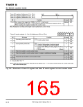
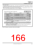
8.4.1 Count source
For timer B2 in the event counter mode, a count source (an external signal into the TB2IN pin, or fX32) can
be selected by using the timer B2 clock source select bit. (See Figure 8.4.2.) Timers B0 and B1 count the
external signals input to the TB0IN and TB1IN pins, respectively.
When fX32 is selected as the count source, the TB2IN pin serves as a programmable I/O port pin or as I/
O pins of other internal peripheral devices, which are multiplexed.
b7 b6 b5 b4 b3 b2 b1 b0
Particular function select register 1 (Address 6316
)
0
0
Function
Bit
0
Bit name
At reset
(Note 1) RW
(Note 2)
(Note 1) RW
(Note 2)
0 : Normal operation.
1 : During execution of STP instruction
STP-instruction-execution
status bit
0 : Normal operation.
WIT-instruction-execution
status bit
1
1 : During execution of WIT instruction
Fix this bit to “0.”
0
2
3
RW
System clock stop select bit
at WIT
0 : In the wait mode, system clock fsys is active.
1 : In the wait mode, system clock fsys is inactive.
0
RW
(Note 3)
0
0
0
RW
—
Fix this bit to “0.”
4
5
6
The value is “0” at reading.
Timer B2 clock source select bit 0 : External signal input to the TB2IN pin is counted.
(Valid in event counter mode.)
RW
1 : fX32 is counted.
(Note 4)
—
The value is “0” at reading.
0
7
Notes 1: At power-on reset, this bit becomes “0.” At hardware reset or software reset, this bit retains the value just before reset.
2: Even when “1” is written, the bit status will not change.
3: Setting this bit to “1” must be performed just before execution of the WIT instruction. Also, after the wait state is termi-
nated, this bit must be cleared to “0” immediately.
4: When using timer B2 in the pulse period/pulse width measurement mode, be sure to clear this bit to “0.”
Fig. 8.4.2 Structure of particular function select register 1
7905 Group User’s Manual Rev.1.0
8-15

 RENESAS [ RENESAS TECHNOLOGY CORP ]