TIMER A
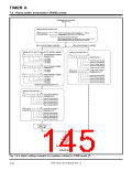
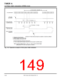
7.6 Pulse width modulation (PWM) mode
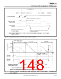
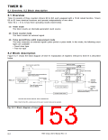
(1 / f
) ꢀ (m + 1) ꢀ (28 – 1)
i
ꢀ Count source
TAi IN pin’s
input signal
(1 / f
i
) ꢀ (m + 1)
ꢀ 8-bit prescaler’s
underflow signal
(1 / f) ꢀ (m + 1) ꢀ (n)
i
PWM pulse output
from TAi OUT pin
Timer Ai interrupt
request bit
Cleared to “0” when interrupt request is accepted or cleared by software.
fi: Frequency of count source
n: Reload register’s high-order 8 bits
m: Reload register’s low-order 8 bits
ꢀ The 8-bit prescaler counts the count source.
ꢀ The 8-bit pulse width modulator counts the 8-bit prescaler’s underflow signal.
Note: The above applies when n = “0216”, m = “0216”, and an external trigger
(falling edge of TAi IN pin’s input signal) is selected.
Fig. 7.6.7 Operation example of 8-bit pulse width modulator
7905 Group User’s Manual Rev.1.0
7-46

 RENESAS [ RENESAS TECHNOLOGY CORP ]