TIMER A
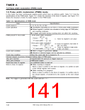
7.6 Pulse width modulation (PWM) mode
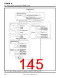
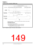
Continued from preceding
Figure 7.6.3
Setting interrupt priority level
b7
b0
Timer Ai interrupt control register (i = 0 to 9)
(Addresses 7516 to 7916, F516 to F916
)
Interrupt priority level select bits
When using interrupts, set these bits to one of levels 1 to 7.
When disabling interrupts, set these bits to level 0.
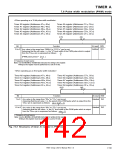
When internal trigger is selected
When external trigger is selected
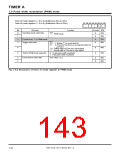
Setting port P6, port P2, and port P4 direction registers
Setting count start bit to “1”
b7
b0
b7
b0
Port P6 direction register
(Address 1016
)
(Address 4016
)
Pin TA0IN
Pin TA1IN
Pin TA2IN
Pin TA3IN
Timer A0 count start bit
Timer A1 count start bit
Timer A2 count start bit
Timer A3 count start bit
Timer A4 count start bit
b7
b7
b0
b0
Port P2 direction register
(Address 816
)
b7
b0
Pin TA4IN
Pin TA9IN
Count start register 1
(Address 4116
)
Port P4 direction register
Timer A5 count start bit
Timer A6 count start bit
Timer A7 count start bit
Timer A8 count start bit
Timer A9 count start bit
(Address C16
)
Pin TA5IN
Pin TA6IN
Pin TA7IN
Pin TA8IN
Clear the corresponding bit to “0.”
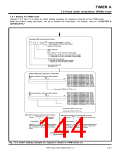
Setting count start bit to “1”
b7
b0
Count start register 0
(Address 4016
)
Timer A0 count start bit
Timer A1 count start bit
Timer A2 count start bit
Timer A3 count start bit
Timer A4 count start bit
b7
b0
Count start register 1
(Address 4116
)
Timer A5 count start bit
Timer A6 count start bit
Timer A7 count start bit
Timer A8 count start bit
Timer A9 count start bit
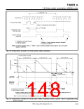
Trigger input
to TAi IN pin
Trigger generated
Count starts.
Fig. 7.6.4 Initial setting example for registers related to PWM mode (2)
7905 Group User’s Manual Rev.1.0
7-42

 RENESAS [ RENESAS TECHNOLOGY CORP ]