TIMER A
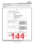
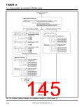
7.6 Pulse width modulation (PWM) mode
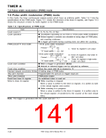
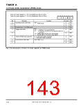
Timer Ai mode register (i = 0 to 4) (Addresses 5616 to 5A16)
Timer Ai mode register (i = 5 to 9) (Addresses D616 to DA16)
b7 b6 b5 b4 b3 b2 b1 b0
1 1 1
Bit
0
Bit name
Function
At reset R/W
b1 b0
Operating mode select bits
0
0
0
0
RW
RW
RW
RW
1 1 : PWM mode
1
2
Fix this bit to “1” in PWM mode.
b4 b3
3
Trigger select bits
0 0 :
0 1 :
Writing “1” to count start bit
(TAiIN pin functions as a programmable I/O
port pin.)
4
5
0
0
RW
RW
1 0 : Falling edge of TAiIN pin’s input signal
1 1 : Rising edge of TAiIN pin’s input signal
0 : 16-bit pulse width modulator
1 : 8-bit pulse width modulator
16/8-bit PWM mode select bit
Count source select bits
See Table 7.2.3.
6
7
0
0
RW
RW
Fig. 7.6.2 Structures of timer Ai mode register in PWM mode
7905 Group User’s Manual Rev.1.0
7-40

 RENESAS [ RENESAS TECHNOLOGY CORP ]