TIMER A
7.6 Pulse width modulation (PWM) mode
7.6 Pulse width modulation (PWM) mode
In this mode, the timer continuously outputs pulses which have an arbitrary width. Table 7.6.1 lists the
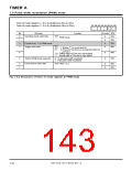
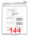
specifications of the PWM mode. Figure 7.6.1 shows the structure of the timer Ai register, and Figure 7.6.2
shows the structure of timer Ai mode register in the PWM mode.
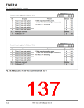
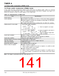
Table 7.6.1 Specifications of PWM mode
Specifications
Item
f
1
, f , f16, f64, f512, or f4096
2
Count source f
i
ꢀ Countdown (operating as an 8-bit or 16-bit pulse width modulator)
ꢀ Reload register’s contents are reloaded at rising edge of PWM pulse,
and counting continues.
Count operation
ꢀ A trigger generated during counting does not affect the counting.
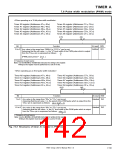
<16-bit pulse width modulator>
PWM period/“H” level width
(216–1)
Period =
[s]
n
f
i
n : Timer Ai register’s set value
“H” level width =
[s]
f
i
<8-bit pulse width modulator>
m:Timer Ai register’s low-order 8
bits’ set value
n : Timer Ai register’s high-order
8 bits’ set value
(m + 1)(28–1)
Period =
[s]
f
i
n(m + 1)
“H” level width =
[s]
f
i
Count start condition
Count stop condition
ꢀ When a trigger is generated. (Note)
ꢀ Internal or external trigger can be selected by software.
When the count start bit is cleared to “0.”
Interrupt request occurrence timing At falling edge of PWM pulse
TAiIN pin’s function
Programmable I/O port pin or trigger input pin
TAiOUT pin’s function
PWM pulse output
Read from timer Ai register
Write to timer Ai register
An undefined value is read out.
ꢀ While counting is stopped
When a value is written to the timer Ai register, it is written to both
of the reload register and counter.
ꢀ While counting is in progress
When a value is written to the timer Ai register, it is written only to
the reload register. (Transferred to the counter at the next reload
time.)
Note: The trigger is generated with the count start bit = “1.”
7905 Group User’s Manual Rev.1.0
7-38

 RENESAS [ RENESAS TECHNOLOGY CORP ]