ALC5642-VF
Datasheet
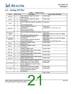
6.2. Analog I/O Pins
Table 2. Analog I/O Pins
Name
Type Pin
Description
Characteristic Definition
Analog output
Line output type (single-end output)
LOUTR
O
O
17
16
Right channel
Line output type (single-end output)
Left channel
Analog output
LOUTL
IN2P
Positive differential input for microphone Analog input
2
Left channel line input
I
I
I
I
7
8
5
6
Negative differential input for
microphone 2
Right channel line input
Second jack detection pin
Analog input
JD threshold: VIL = 0.2V, VIH = 1.2V
IN2N/JD2
Positive differential input for microphone Analog input
1
First digital microphone data input
IN1P/DMIC1_
DAT
Digital input (Only can accept 1.8V digital
signal input)
Negative differential input for
microphone 1
Analog input
IN1N/DMIC2
_DAT/JD1
Digital input (Only can accept 1.8V digital
signal input)
JD threshold: VIL = 0.2V, VIH = 1.2V
Analog output
Second digital microphone data input
First jack detection pin
Headphone amplifier output
Right channel
HPO_R
HPO_L
O
O
O
O
O
O
26
28
1
Headphone amplifier output
Left channel
Analog output
Analog output
Analog output
Analog output
Analog output
Speaker amplifier output
Left differential positive output channel
Speaker amplifier output
Left differential negative output channel
Speaker amplifier output
Right differential positive output channel
Speaker amplifier output
Right differential negative output channel
Mono output with driving capability
Differential positive output channel
Positive differential or single-end input
for microphone 3
SPO_LP
SPO_LN
SPO_RP
SPO_RN
48
45
47
Analog output
Analog input
MONOP/IN3P I/O
13
14
Mono output with driving capability
Differential negative output channel
Analog output
Analog input
MONON/IN3
I/O
N
Negative differential input for
microphone 3
Total: 14 Pins
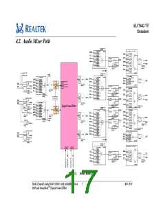
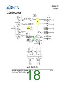
Multi-Channel Audio Hub/CODEC with embedded Voice
DSP and SounzRealTM Digital Sound Effect
9
Rev. 0.93

 REALTEK [ Realtek Semiconductor Corp. ]