RS232C interface to a PC or other device, with the aid of a
MAX232 type driver/receiver circuit.
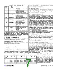
Table 3-1 ASCII Command Set
ASCII
Code
Hex
Purpose
Code
Button State.
Returns 4 bytes of on/off status
for all buttons
3.2 COMMAND SET
s
0x73
0x53
The 60320 requires ASCII commands over the serial port in
order to send result data. The commands must be one of
those listed in Table 3-1. None of the commands should ever
be terminated with a CR or LF code. Each command is
self-contained and requires no terminator.
Identification command.
QT60320D responds with
signature "32000xx" where xx is
the code revision
S
Error reporting.
3.2.1 's' COMMAND - BUTTON
S
TATE
e
0x65
Returns 4 bytes corresponding to
error bits for each key
Data Signal Reporting.
Returns signal and reference for
the key at location X Y
Offset,Coarse Cal Reporting.
Returns coarse and offset values
for the key at location X Y
Settings Reporting.
Returns Gain and Threshold
levels for chosen key at A
Settings Write.
Writes the Gain or Threshold
value v for the chosen key at A
Port Write.
(Hex code 0x73) After an ‘s’ character is received, the E6S3
reports back the touch-state of the buttons; it responds by
transmitting back 4 bytes of data containing a total of 32 data
bits, where each bit represents the state of one button (Table
3-2).
/dXY
/DXY
/eA
/EAv
Ov
0x2F 0x64 X Y
0x2F 0x44 X Y
0x2F 0x65 A
0x2F 0x45 A v
0x4F v
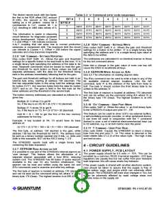
Each byte holds the state of the buttons contained in a Y
column. The first byte corresponds to column Y1 while the
4th byte corresponds to column Y4. Bit 0 of each byte holds
the state of the button corresponding to X1; bit 7 holds the
state corresponding to X8. Multiple key presses will show as
multiple bits being set in the data stream. The device
supports n-key rollover to a limit of all 32 keys.
Example: The key at intersection X5/Y2 appears at bit 4 in
the second byte; if key X5/Y2 is touched the bit is set. All
untouched bits register as a ‘0'.
Writes byte value v to the user
output pins O1..O8
Port Read.
Reads back the 4 bits of user port
pins I1..I4
I
0x49
3.2.2 'S' COMMAND - IDENTIFICATION
R
EPORTING
(Hex code 0x53) The E6S3 board responds with the 7-byte
ASCII signature "32000xx" where x is the code revision.
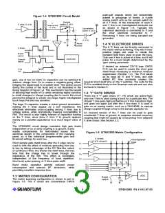
Yb is used to gate another analog switch to ground, and if
the switches used do not have a break-before-make
characteristic, they should be guard-banded as shown to
prevent cross conduction from Cs to ground.
3.2.3 'e' COMMAND - ERROR
R
EPORTING
(Hex code 0x65) This command allows the host to retrieve
the error status bits for all buttons, in 4 consecutive bytes
(Table 3-3). The byte and bit sequences are identical to that
described in conjunction with the 's' command (see prior).
3 SERIAL INTERFACE
The QT60320D uses a serial interface to a host. This port
uses a simple ASCII protocol described in this section.
The appropriate bits are set high when errors are detected.
The error may be caused either by a short across the button
or an open circuit at the button.
3.1 SERIAL PORT SPECIFICATIONS
The QT60320D uses a full-duplex asynchronous serial
interface with the following specifications:
3.2.4 '/dXY' COMMAND - DATA
S
IGNAL
R
EPORTING
(Hex codes 0x2F 0x64 X Y) This sequence reports back the
signal level and reference value for the key chosen. X and Y
are zero-referenced binary (not ASCII) values in the range
0..7 for X and 0..3 for Y to indicate the button for which data
is requested. If X=0 and Y=0, the device reports back with
the data for key X1 Y1. If X=3 and Y=1, the key selected is
X4 Y2. The last key is X8 Y4, so the highest /dXY command
is /d73 where '7' and '3' are in binary.
Baud Rate:
Parity:
Length:
9600
None
8 bits
1
Stop bits:
These specifications hold if the device is operated from an
8MHz crystal or resonator.
The device reports back with two bytes: the first is the
reference level, the second is the signal level. Both are
binary bytes of range 0..255.
The port can be directly connected to a like port of a host
MCU, or transmitted over a length of cable on a standard
3.2.5 '/DXY' COMMAND - OFFSET
&
C
OARSE
R
EPORTING
Table 3-2 's' Command button state responses
(Hex codes 0x2F 0x44 X Y) This
sequence reports back the fine offset
(R2R DAC) and coarse (Cz1, Cz2
bucking caps) values for the key
chosen. X and Y are zero- referenced
binary (not ASCII) values in the range
0..7 for X and 0..3 for Y to indicate the
button for which data is requested.
BIT #
BYTE #
7
6
5
4
3
2
1
0
1
X8/Y1
X8/Y2
X8/Y3
X8/Y4
X7/Y1
X7/Y2
X7/Y3
X7/Y4
X6/Y1
X6/Y2
X6/Y3
X6/Y4
X5/Y1
X5/Y2
X5/Y3
X5/Y4
X4/Y1
X4/Y2
X4/Y3
X4/Y4
X3/Y1
X3/Y2
X3/Y3
X3/Y4
X2/Y1
X2/Y2
X2/Y3
X2/Y4
X1/Y1
X1/Y2
X1/Y3
X1/Y4
2
3
4
LQ
7
QT60320D R1.11/12.07.03

 QUANTUM [ QUANTUM RESEARCH GROUP ]