Figure 3-2
Figure 3-3
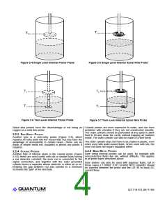
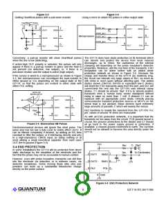
Getting HeartBeat pulses with a pull-down resistor
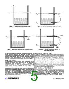
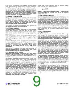
Using a micro to obtain HB pulses in either output state
HeartBeat™ Pulses
2
7
6
5
PORT_M.1
2
3
4
7
6
5
OUT1
OUT2
FILT
SNS2
SNS1
POL
OUT1
OUT2
FILT
SNS2
SNS1
POL
R
R
1
2
PORT_M.2
PORT_M.3
Ro
3
4
Microprocessor
Ro
PORT_M.4
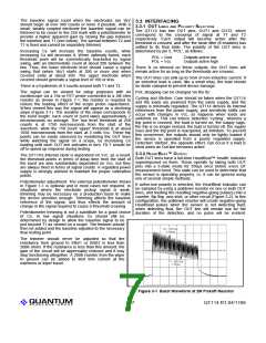
Conversely, a pull-up resistor will show HeartBeat pulses The QT114 does have diode protection on its terminals which
when the line is low (detecting).
can absorb and protect the device from most induced
discharges, up to 20mA; the usefulness of the internal
clamping will depending on the probe insulation's dielectric
properties, thickness, and the rise time of the transients. ESD
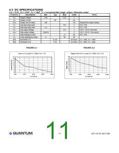
dissipation can be aided further with an added diode
protection network as shown in Figure 3-5. Because the
If active-high OUT polarity is selected, the pulses will only
appear if there is a pull-up resistor in place and the fluid is
not present (no detection, low output), or, if there is a
pull-down resistor and the output is active (high output).
If the sensor is wired to a microprocessor as shown in Figure charge and transfer times of the QT114 are relatively long,
the circuit can tolerate very large values of Re1, as much as
50k ohms in most cases without affecting gain. The added
3-3, the microprocessor can reconfigure the load resistor to
either ground or Vcc depending on the output state of the
QT114, so that the pulses are evident in either state with diodes shown (1N4150, BAV99 or equivalent low-C diodes)
will shunt the ESD transients away from the part, and Re1 will
current-limit the rest into the QT110's own internal clamp
diodes. C1 should be around 10µF if it is to absorb positive
transients from a human body model standpoint without
rising in value by more than 1 volt. If desired C1 can be
replaced with an appropriate zener diode. Directly placing
semiconductor transient protection devices or MOV's on the
sense lead is not advised; these devices have extremely
large amounts of parasitic C which will swamp the sensor.
either POL setting.
GATE OR
MICRO INPUT
2
3
4
7
6
5
CMOS
OUT1
OUT2
FILT
SNS2
SNS1
POL
Co
100pF
CMOS
Re2 functions to isolate the transient from the QT110's Vcc
pin; values of around 1K ohms are reasonable.
100pF
Co
As with all ESD protection networks, it is important that the
transients be led away from the circuit. PCB ground layout is
crucial; the ground connections to the diodes and C1 should
all go back to the power supply ground or preferably, if
available, a chassis ground connected to earth. The currents
should not be allowed to traverse the area directly under the
QT114.
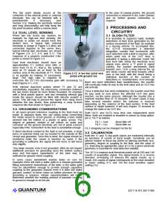
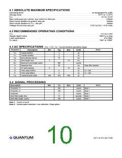
Figure 3-4 Eliminating HB Pulses
Electromechanical devices will ignore this short pulse. The
pulse also has too low a duty cycle to visibly affect LED’s. It
can be filtered completely if desired, by adding an RC time
constant to filter the output, or if interfacing directly and only
to a high-impedance CMOS input, by doing nothing or at
most adding a small noncritical capacitor from each used
OUT line to ground (Figure 3-4).
Vcc
C 10✙F
1
Re
Re
2
1
3.4 ESD PROTECTION
In some installations the QT114 will be protected from direct
static discharge by the insulation of the electrode and the
fact that the probe may not be accessible to human contact.
1
To Electrodes
2
3
4
7
6
5
OUT1
OUT2
FILT
SNS2
SNS1
POL
However, even with probe insulation, transients can still flow
into the electrode via induction, or in extreme cases, via
dielectric breakdown. Some moving fluids (like oils) and
powders can build up a substantial triboelectric charge
directly on the probe surface.
C
S
8 Gnd
Figure 3-5 ESD Protection Network
LQ
8
QT114 R1.04/1106

 QUALCOMM [ QUALCOMM INCORPORATED ]