TOP252-262
Line Overvoltage Shutdown (OV)
clamp network, bias winding return or power traces from other
converters. If the line sensing features are used, then the sense
resistors must be placed within 10 mm of the V-pin to minimize
the V-pin node area. The DC bus should then be routed to the
line sense resistors. Note that external capacitance must not
be connected to the V-pin as this may cause misoperaton of the
V pin related functions.
The same resistor used for UV also sets an overvoltage
threshold, which, once exceeded, will force TOPSwitch-HX to
stop switching instantaneously (after completion of the current
switching cycle). If this condition lasts for at least 100 μs, the
TOPSwitch-HX output will be forced into off state. Unlike with
TOPSwitch-GX, however, when the line voltage is back to
normal with a small amount of hysteresis provided on the OV
threshold to prevent noise triggering, the state machine sets to
S13 and forces TOPSwitch-HX to go through the entire auto-
restart sequence before attempting to switch again. The ratio
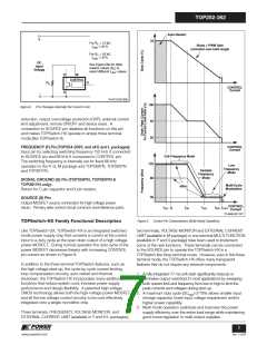
of OV and UV thresholds is preset at 4.5, as can be seen in
Figure 12. When the MOSFET is off, the rectified DC high
voltage surge capability is increased to the voltage rating of the
MOSFET (700 V), due to the absence of the reflected voltage
and leakage spikes on the drain. The OV feature can be
disabled independent of the UV feature.
Hysteretic or Latching Output Overvoltage Protection (OVP)
The detection of the hysteretic or latching output overvoltage
protection (OVP) is through the trigger of the line overvoltage
threshold. The V-pin or M-pin voltage will drop by 0.5 V, and
the controller measures the external attached impedance
immediately after this voltage drops. If IV or IM exceeds IOV(LS)
(336 μA typical) longer than 100 μs, TOPSwitch-HX will latch
into a permanent off state for the latching OVP. It only can be
reset if VV or VM goes below 1 V or VC goes below the power-
up-reset threshold (VC(RESET)) and then back to normal.
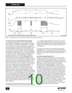
In order to reduce the no-load input power of TOPSwitch-HX
designs, the V-pin (or M-pin for P Package) operates at very low
currents. This requires careful layout considerations when
designing the PCB to avoid noise coupling. Traces and
components connected to the V-pin should not be adjacent to
any traces carrying switching currents. These include the drain,
If IV or IM does not exceed IOV(LS) or exceeds no longer than
100 μs, TOPSwitch-HX will initiate the line overvoltage and the
hysteretic OVP. Their behavior will be identical to the line
overvoltage shutdown (OV) that has been described in detail in
the previous section.
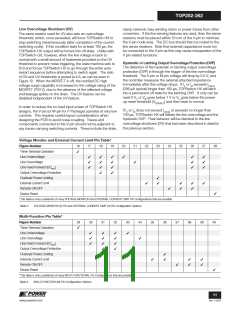
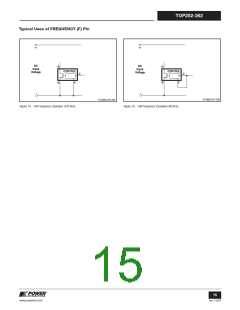
Voltage Monitor and External Current Limit Pin Table*
Figure Number
16
17
18
19
20
21
22
23
24
25
26
27
28
Three Terminal Operation
Line Undervoltage
✓
✓
✓
✓
✓
✓
✓
✓
✓
✓
✓
✓
✓
✓
✓
✓
✓
✓
✓
Line Overvoltage
✓
Line Feed-Forward (DCMAX
)
Output Overvoltage Protection
Overload Power Limiting
External Current Limit
Remote ON/OFF
✓
✓
✓
✓
✓
✓
✓
✓
✓
Device Reset
✓
*This table is only a partial list of many VOLTAGE MONITOR and EXTERNAL CURRENT LIMIT Pin Configurations that are possible.
Table 2. VOLTAGE MONITOR (V) Pin and EXTERNAL CURRENT LIMIT (X) Pin Configuration Options.
Multi-Function Pin Table*
Figure Number
29
30
31
32
33
34
35
36
37
38
39
40
Three Terminal Operation
Line Undervoltage
Line Overvoltage
✓
✓
✓
✓
✓
✓
✓
✓
✓
✓
✓
✓
✓
✓
Line Feed-Forward (DCMAX
)
Output Overvoltage Protection
Overload Power Limiting
External Current Limit
Remote ON/OFF
✓
✓
✓
✓
✓
✓
✓
✓
Device Reset
✓
*This table is only a partial list of many MULTI-FUNCTIONAL Pin Configurations that are possible.
Table 3. MULTI-FUNCTION (M) Pin Configuration Options.
11
www.powerint.com
Rev. F 01/09

 POWERINT [ Power Integrations ]