TNY263-268
70 °C (typical) is provided to prevent overheating of the PC
Line Under-Voltage Sense Circuit
board due to a continuous fault condition.
TheDClinevoltagecanbemonitoredbyconnectinganexternal
resistor from the DC line to the EN/UV pin. During power-up
or when the switching of the power MOSFET is disabled in
auto-restart, the current into the EN/UVpin must exceed 49 µA
to initiate switching of the power MOSFET. During power-up,
this is accomplished by holding the BYPASS pin to 4.8Vwhile
the line under-voltage condition exists. The BYPASS pin then
rises from 4.8 V to 5.8 V when the line under-voltage condition
goes away. When the switching of the power MOSFET is
disabledinauto-restartmodeandalineunder-voltagecondition
exists, the auto-restart counter is stopped. This stretches the
disable time beyond its normal 850 ms until the line under-
voltage condition ends.
Current Limit
ThecurrentlimitcircuitsensesthecurrentinthepowerMOSFET.
When this current exceeds the internal threshold (ILIMIT), the
powerMOSFETisturnedofffortheremainderofthatcycle.The
current limit state machine reduces the current limit threshold
by discrete amounts under medium and light loads.
The leading edge blanking circuit inhibits the current limit
comparator for a short time (tLEB) after the power MOSFET is
turned on. This leading edge blanking time has been set so that
currentspikescausedbycapacitanceandsecondary-siderectifier
reverse recovery time will not cause premature termination of
the switching pulse.
The line under-voltage circuit also detects when there is
no external resistor connected to the EN/UV pin (less than
~ 2 µAinto the pin). In this case the line under-voltage function
is disabled.
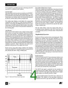
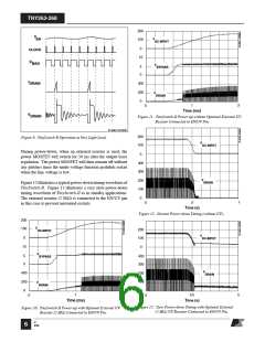
Auto-Restart
In the event of a fault condition such as output overload, output
short circuit, or an open loop condition, TinySwitch-II enters
into auto-restart operation. An internal counter clocked by the
oscillator gets reset every time the EN/UV pin is pulled low. If
the EN/UVpin is not pulled low for 50 ms, the power MOSFET
switching is normally disabled for 850 ms (except in the case of
line under-voltage condition, in which case it is disabled until
the condition is removed). The auto-restart alternately enables
anddisablestheswitchingofthepowerMOSFETuntilthefault
condition is removed. Figure 5 illustrates auto-restart circuit
operation in the presence of an output short circuit.
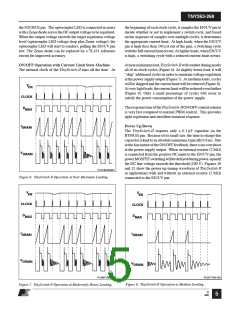
TinySwitch-II Operation
TinySwitch-II devices operate in the current limit mode. When
enabled, the oscillator turns the power MOSFET on at the
beginning of each cycle. The MOSFET is turned off when the
current ramps up to the current limit or when the DCMAX limit is
reached. Since the highest current limit level and frequency of
a TinySwitch-II design are constant, the power delivered to the
loadisproportionaltotheprimaryinductanceofthetransformer
and peak primary current squared. Hence, designing the supply
involves calculating the primary inductance of the transformer
for the maximum output power required. If the TinySwitch-II
is appropriately chosen for the power level, the current in the
calculated inductance will ramp up to current limit before the
DCMAX limit is reached.
In the event of a line under-voltage condition, the switching
of the power MOSFET is disabled beyond its normal 850 ms
time until the line under-voltage condition ends.
Enable Function
V
300
DRAIN
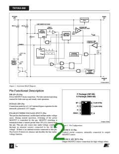
TinySwitch-IIsensestheEN/UVpintodeterminewhetherornot
to proceed with the next switching cycle as described earlier.
The sequence of cycles is used to determine the current limit.
Onceacycleisstarted,italwayscompletesthecycle(evenwhen
the EN/UV pin changes state half way through the cycle). This
operation results in a power supply in which the output voltage
ripple is determined by the output capacitor, amount of energy
per switch cycle and the delay of the feedback.
200
100
0
10
V
DC-OUTPUT
5
The EN/UV pin signal is generated on the secondary by
comparing the power supply output voltage with a reference
voltage. The EN/UV pin signal is high when the power supply
output voltage is less than the reference voltage.
0
1000
2000
0
Time (ms)
In a typical implementation, the EN/UV pin is driven by an
optocoupler. The collector of the optocoupler transistor is
connected to the EN/UV pin and the emitter is connected to
Figure 5. TinySwitch-II Auto-Restart Operation.
G
4/05
4

 POWERINT [ Power Integrations ]