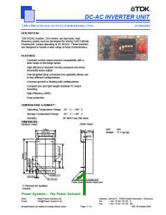
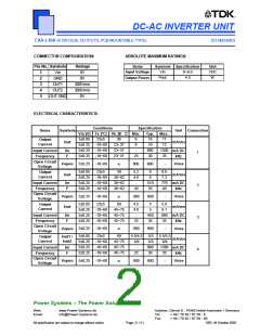
DC-AC INVERTER UNIT
(STANDARD)
CXA-L10A (4.5W DUAL OUTPUTS, PCB MOUNTABLE TYPE)
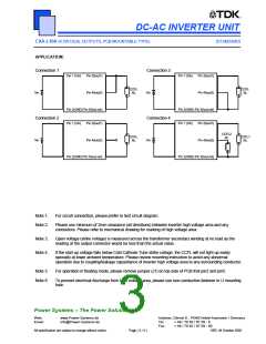
APPLICATION:
Connection 1
Connection 3
Pin 1 (Vin)
Pin 3(Iout1)
Pin 4(Iout2)
Pin 1 (Vin)
Pin 3(Iout1)
Pin 4(Iout2)
CCFL
RL
CCFL
RL
Vin
Vin
Pin 2(GND) Pin 5(Iout-ret)
Pin 2(GND) Pin 5(Iout-ret)
Connection 2
Connection 4
Pin 1 (Vin)
Pin 3(Iout1)
Pin 4(Iout2)
Pin 1 (Vin)
Pin 3(Iout1)
Pin 4(Iout2)
CCFL2
RL
CCFL
RL
CCFL1
RL
Vin
Vin
Pin 2(GND) Pin 5(Iout-ret)
Pin 2(GND) Pin 5(Iout-ret)
Note 1.
Note 2.
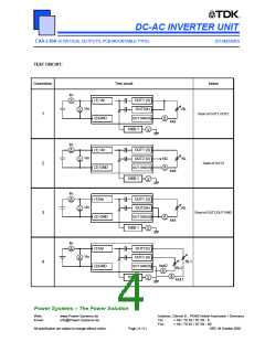
For circuit connection, please prefer to test circuit diagram.
Please use minimum of 2mm clearance (all directions) between inverter high voltage area and any
conductors. Please refer to mechanical drawing for marking of high voltage area.
Note 3.
Note 4.
Open voltage (strike voltage) is measured across the transformer secondary winding at no load as the
reading at the output connector would be less than the actual value.
If the start up voltage falls below Cold Cathode Tube strike voltage, the CCFL will not light up easily
specially at lower ambient temperature. Please review mounting instruction to avoid any abnormal
operation due to coupling/leakage capacitance of inverter high voltage area to any surrounding conductor.
Note 5.
Note 6.
For operation in floating mode, please remove jumper (J1) on top side of PCB that pin2 and pin5.
To prevent electrical discharge from high voltage area, please use non-conductive fastener in U mounting
hole.
Power Systems – The Power Solution
Web:
www.Power-Systems.de
Info@Power-Systems.de
Address: Dörnet 8 ; 74360 Ilsfeld-Auenstein / Germany
Email:
Tel. :
Fax:
+ 49 / 70 62 / 67 59 - 6
+ 49 / 70 62 / 67 59 - 80
All specification are subject to change without notice.
Page ( 3 / 4 )
VER, 04 October 2002

 POWER-SYSTEMS [ POWER SYSTEMS GMBH+CO.KG ]