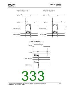
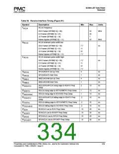
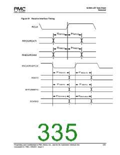
S/UNI®-JET Data Sheet
Released
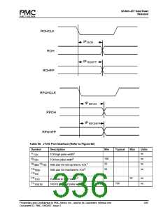
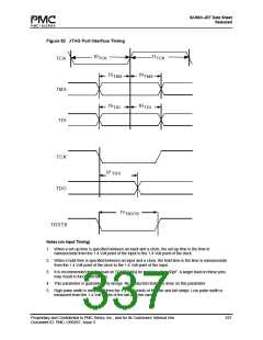
Figure 82 JTAG Port Interface Timing
t0
t1
TCK
TCK
TCK
TMS
TDI
tS
tS
tH
tH
TMS
TDI
TMS
TDI
TCK
TDO
tP
TDO
tV
TRSTB
TRSTB
Notes (on Input Timing)
1. When a set-up time is specified between an input and a clock, the set-up time is the time in
nanoseconds from the 1.4 Volt point of the input to the 1.4 Volt point of the clock.
2. When a hold time is specified between an input and a clock, the hold time is the time in nanoseconds
from the 1.4 Volt point of the clock to the 1.4 Volt point of the input.
3. It is recommended that the load on TGAPCLK[x] be kept less than 50pF. A larger load on these pins
may result in functional failures.
4. This parameter is guaranteed by design. No production tests are done on this parameter.
5. High pulse width is measured from the 1.4 Volt points of the rise and fall ramps. Low pulse width is
measured from the 1.4 Volt points of the fall and rise ramps.
Proprietary and Confidential to PMC-Sierra, Inc., and for its Customers’ Internal Use
Document ID: PMC-1990267, Issue 3
337

 PMC [ PMC-SIERRA, INC ]