S/UNI®-ATLAS-3200 Telecom Standard Product Data Sheet
Preliminary
The Cfg1 configuration is selected if the per-connection PolicingConfiguration[2:0]=000. The
Cfg2 configuration is selected if the per-connection PolicingConfigSelect[2:0] =001
GCRA1[7:0]
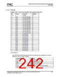
The following table indicates upon which cell streams the first policing instance acts:
Cell Type RM
Segment OAM
End-to-End OAM
User
0
CLP Bit
0
1
0
1
0
1
1
Reg Bit
GCRA1 GCRA1 GCRA1 GCRA1 GCRA1 GCRA1 GCRA1 GCRA1
[0] [1] [2] [3] [4] [5] [6] [7]
A logic 1 written to any of the GCRA1[7:0] bits enables GCRA1 policing for that particular
cell stream. For example, to enable cell rate policing for GCRA1 on the user CLP=0+1 cell
stream, the register configuration would be GCRA1[7:0]=11000000. If GCRA1[7:0] =
00000000, the first GCRA policing instance is globally disabled.
Note that F5 OAM and RM cells are considered user cells when being policed at the F4 level,
which occurs if the VC is an F4, or if the VP_POLICE feature is being used.
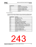
GCRA2[7:0]
These register bits control upon which cell streams the second GCRA instance acts. These
register bits are programmed in exactly the same manner as described above.
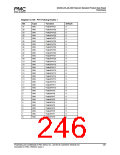
Register 0x132: Connection Policing Configuration 3 & 4
Register 0x133: Connection Policing Configuration 5 & 6
Register 0x134: Connection Policing Configuration 7 & 8
Proprietary and Confidential to PMC-Sierra, Inc., and for its Customers’ Internal Use
Document ID: PMC-1990553, Issue 4
245

 PMC [ PMC-SIERRA, INC ]