Philips Semiconductors
Preliminary specification
Power stage 2 × 50 W class-D audio
amplifier
TDA8926
15.1 BTL application
When using the system in a mono BTL application (for more output power), the inputs of both channels of the PWM
modulator must be connected in parallel; the phase of one of the inputs must be inverted. In principle the loudspeaker
can be connected between the outputs of the two single-ended demodulation filters.
15.2 Package ground connection
The heatsink of the TDA8926J is connected internally to VSS
.
15.3 Output power
The output power in single-ended applications can be estimated using the formula
2
RL
× V × (1 – tW(min) × fosc
)
------------------------------------------------
P
(RL + Rds(on) + Rs)
Po(1%)
=
--------------------------------------------------------------------------------------------------------------------------
2 × RL
[VP × (1 – tW(min) × fosc)]
The maximum current I O(max)
=
should not exceed 5 A.
---------------------------------------------------------------
RL + Rds(on) + Rs
The output power in BTL applications can be estimated using the formula
2
RL
× 2V × (1 – tW(min) × fosc
)
----------------------------------------------------------
P
RL + 2 × (Rds(on) + Rs)
P o(1%)
=
---------------------------------------------------------------------------------------------------------------------------------------
2 × RL
[2VP × (1 – tW(min) × fosc)]
The maximum current I O(max)
=
should not exceed 5 A.
--------------------------------------------------------------------
RL + 2 × (Rds(on) + Rs)
Where:
RL = load impedance
Rs = series resistance of filter coil
Po(1%) = output power just at clipping
The output power at THD = 10%: Po(10%) = 1.25 × Po(1%)
.
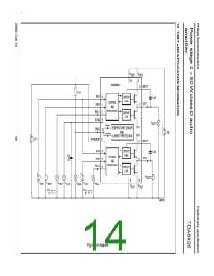
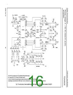
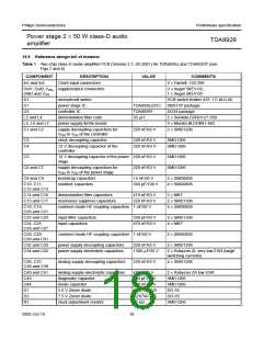
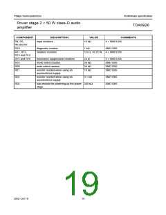
15.4 Reference design
The reference design for a two-chip class-D audio amplifier for TDA8926J and controller TDA8929T is shown in Fig.7.
The Printed-Circuit Board (PCB) layout is shown in Fig.8. The bill of materials is given in Table 1.
2002 Oct 10
15

 NXP [ NXP ]