Philips Semiconductors
Preliminary specification
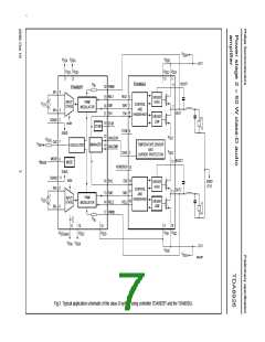
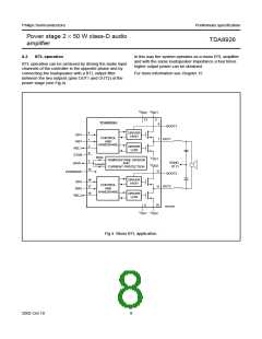
Power stage 2 × 50 W class-D audio
amplifier
TDA8926
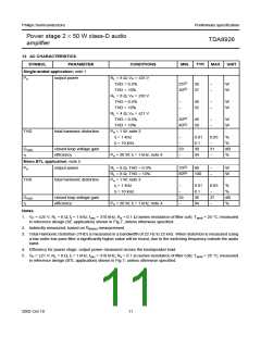
13 AC CHARACTERISTICS
SYMBOL
PARAMETER
CONDITIONS
MIN.
TYP. MAX. UNIT
Single-ended application; note 1
Po
output power
RL = 8 Ω; VP = ±25 V
THD = 0.5%
THD = 10%
25(2)
30(2)
30
37
−
−
W
W
RL = 8 Ω; VP = ±30 V
THD = 0.5%
−
−
40
52
−
−
W
W
THD = 10%
RL = 4 Ω; VP = ±21 V
THD = 0.5%
30(2)
40(2)
40
50
−
−
W
W
THD = 10%
THD
total harmonic distortion
Po = 1 W; note 3
fi = 1 kHz
−
0.01
0.1
30
0.05
−
%
%
dB
%
fi = 10 kHz
−
Gv(cl)
closed-loop voltage gain
efficiency
29
−
31
−
η
Po = 30 W; fi = 1 kHz; note 4
94
Mono BTL application; note 5
Po
output power
RL = 8 Ω; THD = 0.5%
RL = 8 Ω; THD = 10%
Po = 1 W; note 3
fi = 1 kHz
70(2)
80(2)
80
−
−
W
W
100
THD
total harmonic distortion
−
0.01
0.1
36
0.05
−
%
%
dB
%
fi = 10 kHz
−
Gv(cl)
closed loop voltage gain
efficiency
35
−
37
−
η
Po = 30 W; fi = 1 kHz; note 4
94
Notes
1. VP = ±25 V; RL = 8 Ω; fi = 1 kHz; fosc = 310 kHz; Rs = 0.1 Ω (series resistance of filter coil); Tamb = 25 °C; measured
in reference design (SE application) shown in Fig.7; unless otherwise specified.
2. Indirectly measured; based on Rds(on) measurement.
3. Total Harmonic Distortion (THD) is measured in a bandwidth of 22 Hz to 22 kHz. When distortion is measured using
a low-order low-pass filter a significantly higher value will be found, due to the switching frequency outside the audio
band.
4. Efficiency for power stage; output power measured across the loudspeaker load.
5. VP = ±21 V; RL = 8 Ω; fi = 1 kHz; fosc = 310 kHz; Rs = 0.1 Ω (series resistance of filter coil); Tamb = 25 °C; measured
in reference design (BTL application) shown in Fig.7; unless otherwise specified.
2002 Oct 10
11

 NXP [ NXP ]