PCF8583
NXP Semiconductors
Clock and calendar with 240 x 8-bit RAM
7. Functional description
The PCF8583 contains a 256 by 8 bit RAM with an 8 bit auto-increment address register,
an on-chip 32.768 kHz oscillator circuit, a frequency divider, a serial two-line bidirectional
I2C-bus interface, and a Power-On Reset (POR) circuit.
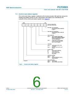
The first 16 bytes of the RAM (memory addresses 00h to 0Fh) are designed as
addressable 8 bit parallel special function registers. The first register (memory
address 00h) is used as a control and status register. The memory addresses 01h to 07h
are used as counters for the clock function. The memory addresses 08h to 0Fh may be
programmed as alarm registers or used as free RAM locations, when the alarm is
disabled.
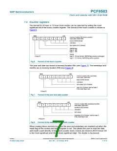
7.1 Counter function modes
When the control and status register is programmed, a 32.768 kHz clock mode, a 50 Hz
clock mode or an event-counter mode can be selected.
In the clock modes the hundredths of a second, seconds, minutes, hours, date, month
(four year calendar) and weekday are stored in a Binary Coded Decimal (BCD) format.
The timer register stores up to 99 days. The event counter mode is used to count pulses
applied to the oscillator input (OSCO left open-circuit). The event counter stores up to 6
digits of data.
When one of the counters is read (memory locations 01h to 07h), the contents of all
counters are strobed into capture latches at the beginning of a read cycle. Therefore,
faulty reading of the counter during a carry condition is prevented.
When a counter is written, other counters are not affected.
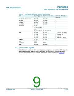
7.2 Alarm function modes
By setting the alarm enable bit of the control and status register the alarm control register
(address 08h) is activated.
By setting the alarm control register, a dated alarm, a daily alarm, a weekday alarm, or a
timer alarm may be programmed. In the clock modes, the timer register (address 07h)
may be programmed to count hundredths of a second, seconds, minutes, hours, or days.
Days are counted when an alarm is not programmed.
Whenever an alarm event occurs the alarm flag of the control and status register is set. A
timer alarm event will set the alarm flag and an overflow condition of the timer will set the
timer flag. The open-drain interrupt output is switched on (active LOW) when the alarm or
timer flag is set (enabled). The flags remain set until directly reset by a write operation.
When the alarm is disabled (bit 2 of control and status register set logic 0) the alarm
registers at addresses 08h to 0Fh may be used as free RAM.
PCF8583
All information provided in this document is subject to legal disclaimers.
© NXP B.V. 2010. All rights reserved.
Product data sheet
Rev. 06 — 6 October 2010
5 of 37

 NXP [ NXP ]