PCF8574; PCF8574A
NXP Semiconductors
Remote 8-bit I/O expander for I2C-bus with interrupt
10. Application design-in information
10.1 Bidirectional I/O expander applications
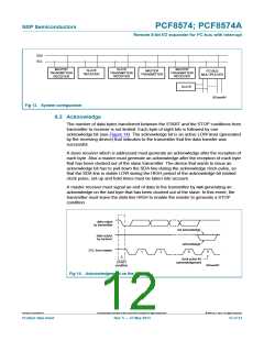
In the 8-bit I/O expander application shown in Figure 15, P0 and P1 are inputs, and
P2 to P7 are outputs. When used in this configuration, during a write, the input (P0 and
P1) must be written as HIGH so the external devices fully control the input ports.
The desired HIGH or LOW logic levels may be written to the ports used as outputs (P2 to
P7). If 10 A internal output HIGH is not enough current source, the port needs external
pull-up resistor. During a read, the logic levels of the external devices driving the input
ports (P0 and P1) and the previous written logic level to the output ports (P2 to P7) will be
read.
The GPIO also has an interrupt line (INT) that can be connected to the interrupt logic of
the microcontroller. By sending an interrupt signal on this line, the remote I/O informs the
microprocessor that there has been a change of data on its ports without having to
communicate via the I2C-bus.
V
DD
V
DD
V
DD
SDA
SCL
INT
P0
P1
P2
P3
P4
P5
P6
P7
temperature sensor
battery status
CORE
PROCESSOR
control for latch
control for switch
control for audio
control for camera
control for MP3
A0
A1
A2
002aah384
Fig 15. Bidirectional I/O expander application
10.2 How to read and write to I/O expander (example)
In the application example of PCF8574 shown in Figure 15, the microcontroller wants to
control the P3 switch ON and the P7 LED ON when the temperature sensor P0 changes.
1. When the system power on:
Core Processor needs to issue an initial command to set P0 and P1 as inputs and
P[7:2] as outputs with value 1010 00 (LED off, MP3 off, camera on, audio off,
switch off and latch off).
2. Operation:
When the temperature changes above the threshold, the temperature sensor signal
will toggle from HIGH to LOW. The INT will be activated and notifies the ‘core
processor’ that there have been changes on the input pins. Read the input register.
If P0 = 0 (temperature sensor has changed), then turn on LED and turn on switch.
3. Software code:
//System Power on
// write to PCF8574 with data 1010 0011b to set P[7:2] outputs and P[1:0] inputs
<S> <0100 0000> <ACK> <1010 0011> <ACK> <P>//Initial setting for PCF9574
PCF8574_PCF8574A
All information provided in this document is subject to legal disclaimers.
© NXP B.V. 2013. All rights reserved.
Product data sheet
Rev. 5 — 27 May 2013
13 of 33

 NXP [ NXP ]