Philips Semiconductors
Product specification
Voltage regulator diodes
BZD23 series
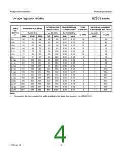
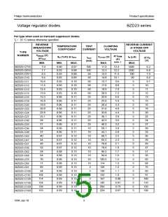
REVERSE
BREAKDOWN
VOLTAGE
REVERSE CURRENT
at STAND-OFF
VOLTAGE
TEMPERATURE
COEFFICIENT
TEST
CURRENT
CLAMPING
VOLTAGE
TYPE
NUMBER
V
(BR)R (V)
at Itest
at IRSM
(A)
note 1
SZ (%/K) at Itest
V(CL)R (V)
IR (µA)
Itest
(mA)
at VR
(V)
MIN.
168
188
208
228
251
280
310
340
370
400
440
480
MIN.
0.09
0.09
0.09
0.09
0.09
0.09
0.09
0.09
0.09
0.09
0.09
0.09
MAX.
0.13
0.13
0.13
0.13
0.13
0.13
0.13
0.13
0.13
0.13
0.13
0.13
MAX.
249
276
305
336
380
419
459
498
537
603
655
707
MAX.
5
5
2
2
2
2
2
2
2
2
2
2
0.60
0.54
0.50
0.45
0.40
0.36
0.33
0.30
0.28
0.25
0.23
0.21
5
5
5
5
5
5
5
5
5
5
5
5
150
160
180
200
220
240
270
300
330
360
390
430
BZD23-C180
BZD23-C200
BZD23-C220
BZD23-C240
BZD23-C270
BZD23-C300
BZD23-C330
BZD23-C360
BZD23-C390
BZD23-C430
BZD23-C470
BZD23-C510
Note
1. Non-repetitive peak reverse current in accordance with “IEC 60-1, Section 8” (10/1000 µs pulse); see Fig.8.
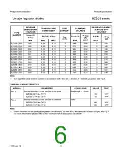
THERMAL CHARACTERISTICS
SYMBOL
Rth j-tp
PARAMETER
CONDITIONS
VALUE
UNIT
thermal resistance from junction to tie-point
BZD23-C3V6 to -C6V8
lead length = 10 mm
87
60
K/W
K/W
BZD23-C7V5 to -C510
Rth j-a
thermal resistance from junction to ambient
BZD23-C3V6 to -C6V8
note 1
145
120
K/W
K/W
BZD23-C7V5 to -C510
Note
1. Device mounted on an epoxy-glass printed-circuit board, 1.5 mm thick; thickness of Cu-layer ≥40 µm, see Fig.7.
For more information please refer to the “General Part of associated Handbook”.
1996 Jun 10
6

 NXP [ NXP ]