Philips Semiconductors
Product data
Single wire CAN transceiver
AU5790
T =T + P * θ
ja
THERMAL CHARACTERISTICS
j
a
d
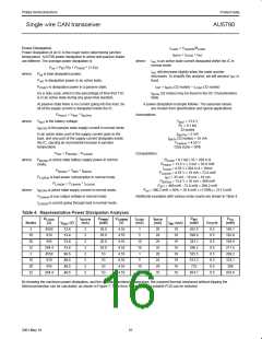
The AU5790 provides protection from thermal overload. When the
IC junction temperature reaches the threshold (≈155 °C), the
AU5790 will disable the transmitter drivers, reducing power
dissipation to protect the device. The transmit function will become
available again after the junction temperature drops. The thermal
shutdown hysteresis is about 5 °C.
where: T is junction temperature (°C);
j
T is ambient temperature (°C);
a
P is dissipated power (W);
d
θ
is thermal resistance (°C/W).
ja
Thermal Resistance
Thermal resistance is the ability of a packaged IC to dissipate heat
to its environment. In semiconductor applications, it is highly
dependant on the IC package, PCBs, and airflow. Thermal
resistance also varies slightly with input power, the difference
between ambient and junction temperatures, and soldering material.
In order to avoid this transmit function shutdown, care must be taken
to not overheat the IC during application. The relationships between
junction temperature, ambient temperature, dissipated power, and
thermal resistance can be expressed as:
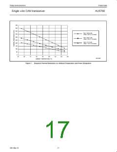
Figures 5 and 6 show the thermal resistance as the function of the
IC package and the PCB configuration, assuming no airflow.
200
150
100
50
very low
conductance
board
low
conductance
board
high
conductance
board
0
0
50
100
150
200
250
SL01249
Cu area on fused pins (mm2)
Figure 5.
SO-8 Thermal Resistance vs. PCB Configuration, Note 1, 2, 3
150
100
50
very low
conductance
board
low
conductance
board
high
conductance
board
0
0
100
200
300
400
500
SL01250
Cu area on fused pins (mm2)
Figure 6.
SO-14 Thermal Resistance vs. PCB Configuration, Note 1, 2, 3
14
2001 May 18

 NXP [ NXP ]