Philips Semiconductors
Product specification
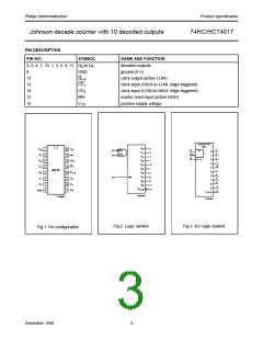
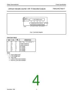
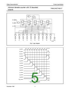
Johnson decade counter with 10 decoded outputs
74HC/HCT4017
AC CHARACTERISTICS FOR 74HC
GND = 0 V; tr = tf = 6 ns; CL = 50 pF
Tamb (°C)
TEST CONDITIONS
74HC
SYMBOL
PARAMETER
UNIT
WAVEFORMS
VCC
(V)
+25
−40 to+85
−40 to+125
min. typ. max. min. max. min. max.
tPHL/ tPLH
propagation delay
CP0 to Qn
63
23
18
230
46
39
290
58
49
345
69
59
ns
ns
ns
ns
ns
ns
ns
ns
ns
ns
ns
ns
MHz
2.0
4.5
6.0
Fig.9
Fig.9
Fig.9
Fig.9
Fig.8
Fig.8
Fig.9
Fig.8
Fig.8
Fig.8
Fig.7
Fig.7
Fig.8
tPHL/ tPLH
propagation delay
CP0 to Q5-9
63
23
18
230
46
39
290
58
49
345
69
59
2.0
4.5
6.0
t
PHL/ tPLH
propagation delay
CP1 to Qn
61
22
18
250
50
43
315
63
54
375
75
64
2.0
4.5
6.0
tPHL/ tPLH
propagation delay
CP1 to Q5-9
61
22
18
250
50
43
315
63
54
375
75
64
2.0
4.5
6.0
tPHL
propagation delay
MR to Q1−9
52
19
15
230
46
39
290
58
49
345
69
59
2.0
4.5
6.0
tPLH
propagation delay
MR to Q5−9, Q0
55
20
16
230
46
39
290
58
49
345
69
59
2.0
4.5
6.0
t
THL/ tTLH
output transition
time
19
7
6
75
15
13
95
19
16
110
22
19
2.0
4.5
6.0
tW
clock pulse width
HIGH or LOW
80
16
14
17
6
5
100
20
17
120
24
20
2.0
4.5
6.0
tW
master reset pulse
width; HIGH
80
16
14
19
7
6
100
20
17
120
24
20
2.0
4.5
6.0
trem
tsu
th
removal time
MR to CP0, CP1
5
5
5
−17
−6
−5
5
5
5
5
5
5
2.0
4.5
6.0
set-up time
CP1 to CP0;
CP0 to CP1
50
10
9
−8
−3
−2
65
13
11
75
15
13
2.0
4.5
6.0
hold time
CP0 to CP1;
CP1 to CP0
50
10
9
17
6
5
65
13
11
75
15
13
2.0
4.5
6.0
fmax
maximum clock
pulse frequency
6.0
30
25
23
70
83
4.8
24
28
4.0
20
24
2.0
4.5
6.0
December 1990
7

 NXP [ NXP ]