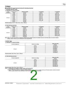
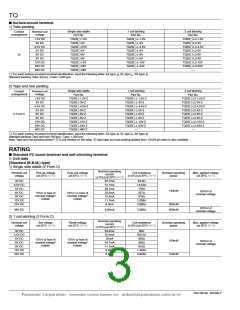
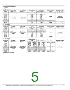
TQ
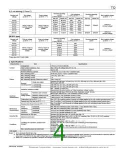
2. Specifications
Characteristics
Item
Specifications
Arrangement
2 Form C
Contact
Initial contact resistance, max.
Contact material
Max. 75 mΩ (By voltage drop 6 V DC 1A)
AgNi type+Au clad
Nominal switching capacity
Max. switching power
2 A 30 V DC, 0.5 A 125 V AC (resistive load)
60 W (DC), 62.5 VA (AC) (resistive load)
220 V DC, 125 V AC
Max. switching voltage
Max. switching current
Min. switching capacity (Reference value)*1
2 A
Rating
10µA 10mV DC
Single side stable
140 mW (1.5 to 12 V DC), 200 mW (24 V DC), 300 mW (48 V DC)
70 mW (1.5 to 12 V DC), 100 mW (24 V DC)
140 mW (1.5 to 12 V DC), 200 mW (24 V DC)
Nominal operating
1 coil latching
power
2 coil latching
Insulation resistance (Initial)
Between open contacts
Min. 1,000MΩ (at 500V DC)
Measurement at same location as “Initial breakdown voltage” section.
1,000 Vrms for 1 min. (Detection current: 10 mA)
1,500 Vrms for 1 min. (Detection current: 10 mA)
1,500 Vrms for 1 min. (Detection current: 10 mA)
1,500 V (10×160µs) (FCC Part 68)
2,500 V (2×10µs) (Bellcore)
Breakdown voltage
Between contact and coil
(Initial)
Between contact sets
Between open contacts
Surge breakdown
voltage (Initial)
Electrical
characteristics
Between contacts and coil
Max. 50°C
Temperature rise (at 20°C 68°F)
(By resistive method, nominal coil voltage applied to the coil; contact carrying current: 2A.)
Max. 4 ms [Max. 4 ms] (Nominal coil voltage applied to the coil, excluding contact bounce
time.)
Operate time [Set time] (at 20°C 68°F)
Release time [Reset time] (at 20°C 68°F)
Max. 4 ms [Max. 4 ms] (Nominal coil voltage applied to the coil, excluding contact bounce
time.) (without diode)
Functional
Shock resistance
Min. 750 m/s2 (Half-wave pulse of sine wave: 6 ms; detection time: 10µs.)
Min. 1,000 m/s2 (Half-wave pulse of sine wave: 6 ms.)
10 to 55 Hz at double amplitude of 3.3 mm (Detection time: 10µs.)
10 to 55 Hz at double amplitude of 5 mm
Destructive
Mechanical
characteristics
Functional
Vibration resistance
Destructive
Mechanical
Min. 108 (at 180 cpm)
Min. 105 (2 A 30 V DC resistive), Min. 2×10⁵ (1 A 30 V DC resistive),
Expected life
Electrical
Min. 105 (0.5 A 125 V AC resistive) (at 20 cpm)
Ambient temperature:
Conditions for operation, transport and storage*2
Max. operating speed (at rated load)
–40°C to +85°C –40°F to +185°F, Max. –40°C to +70°C (2A) Max. –40°F to +158°F (2A);
Humidity: 5 to 85% R.H. (Not freezing and condensing at low temperature)
Conditions
Unit weight
20 cpm
Approx. 2 g .071 oz
Notes: *1 This value can change due to the switching frequency, environmental conditions, and desired reliability level, therefore it is recommended to check this with the
actual load. (TX/TX-S/TX-D relay AgPd contact type are available for low level load switching [10V DC, 10mA max. level])
*2 Refer to 6. Conditions for operation, transport and storage mentioned in AMBIENT ENVIRONMENT (Page 24).
ASCTB14E 201209-T
Panasonic Corporation Automation Controls Business Unit industrial.panasonic.com/ac/e/

 PANASONIC [ PANASONIC ]