T15
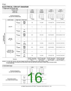
ELECTRICAL CIRCUIT DIAGRAM
1.Toggle type and Rocker type
Number of pole
1-pole
2-pole
3-pole
Available *3
—
4-pole
Available *3
—
Toggle type
Available
Available
Available
Available
Rocker type
Terminal arrangement
(As seen from terminal side)
Keyway
Keyway
Keyway
Keyway
Handle shape
Toggle type Rocker type
Right
Part No.
1-3
1-3, 4-6
—
1-3, 4-6, 7-9
1-3, 4-6, 7-9, 10-12
Keyway
ON-OFF
—
—
—
—
—
—
—
Left
—
—
Keyway
Keyway
—
Right
Part No.
2-3
—
2-3, 5-6
—
2-3, 5-6, 8-9
—
2-3, 5-6, 8-9, 11-12
ON-ON
ON-<ON>
*1
—
—
Left
1-2
2-3
—
1-2, 4-5
2-3, 5-6
—
1-2, 4-5, 7-8
2-3, 5-6, 8-9
—
1-2, 4-5, 7-8, 10-11
2-3, 5-6, 8-9, 11-12
—
Keyway
Keyway
Keyway
Keyway
*2
Right
Part No.
Center
Left
ON-OFF-ON
<ON>-OFF-<ON>
ON-OFF-<ON>
*1
1-2
1-2, 4-5
1-2, 4-5, 7-8
1-2, 4-5, 7-8, 10-11
ON-OFF type does ON-OFF type does ON-OFF type does ON-OFF type does
Remarks
not have a terminal
No. 2.
not have terminal
No. 2 and 5.
not have terminal
No. 2, 5 and 8.
not have terminal
No. 2, 5, 8 and 11.
Remarks: *1. For ON-<ON>, ON-OFF-<ON> type of toggle, if the lever turns to the keyway side, it takes momentary position.
*2. For the rocker type, if the actuator turns to the left side in view of the side where a part number is marked, it takes momentary position.
*3. Only standard type
2. Push-button type
1-pole
2-pole
Terminal arrangement
(As seen from terminal side)
Keyway
Keyway
2-3
1-2
2-3, 5-6
1-2, 4-5
Push-button position
and contact terminal number
Operated
All Rights Reserved © COPYRIGHT Panasonic Electric Works Co., Ltd.

 PANASONIC [ PANASONIC ]