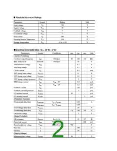
ꢀ Absolute Maximum Ratings
Parameters
Symbol
Rating
Unit
V
Drain voltage
VD
VCC
VFB
VCL
ID
700
Supply voltage
30
V
Feedback voltage
CL terminal voltage
Drain current
7
V
7
500
V
V
Operating Junction Temperature
Storage temperature
Tch
Tstg
150
°C
°C
-55 to +150
ꢀ Electrical Characteristics (Ta = 25°C 3°C)
Parameters
( Control Function )
Oscillator output frequency
Max. Duty cycle
Symbol
Conditions
min
typ
max
Unit
fOSC
MAXDC
VDD
FB:Open
FB:Open
90
-
100
50
5.7
5.1
0.5
12
10
2
110
kHz
%
-
-
-
-
-
-
-
-
-
-
-
-
5
VDD reference voltage
VDD stop voltage
-
V
VUV
-
V
Circuit current
ICC
-
mA
V
VCC charge start voltage
VCC charge stop voltage
VCC charge voltage hysteresis
VDD charge current
VCC(ON)
VCC(OFF)
∆VCC
Ich1
-
-
V
-
V
VDD = 0V
VDD = 4V
-
3.0
1.5
120
3
mA
mA
µA
µA
µA
µA
Ich2
-
Feedback current
IFB
-
Feedback current hystereses
LC terminal current
IFBHYS
ICLMAX
ICLMIN
-
20
-
-
LC terminal current
-
(Protection Function)
Overcurrent detection
ILIMITMIN
ILIMITMAX
VCC(0V)
TOTP
ICL < ICLMIN
ICL > ICLMAX
-
0.05
0.35
20
-
A
-
-
-
-
Overvoltage detection
Overheating detection
Latch reset voltage
(Output Function)
ON resistance
V
°C
V
130
-
140
3
150
-
Vcreset
RDS(ON)
IDSS
VDSS
tr
ID = 0.1 A
VDS = 630 V
ID = 0.25 mA
-
22
-
27
Ω
µA
V
Drain leak current
Drain breakdown voltage
Rise time
-
700
-
250
-
-
-
-
100
50
ns
ns
Fall time
tf
-
(Supply Voltage)
Minimum drain voltage
VD(MIN)
50
-
-
V

 PANASONIC [ PANASONIC ]