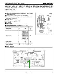
Intelligent Power Devices (IPDs)
MIP0221SY/0222SY/0223SY/0224SY/0225SY/0226SY/0227SY
■ Electrical Characteristics (TC = 25 ± 2°C)
Parameter
Output frequency
Symbol
fOSC
Conditions
min typ max Unit
I
C = 2mA
90
64
100 110 kHz
Control functions
Maximum duty cycle
Minimum duty cycle
MAXDC IC = 2mA
MINDC IC = 10mA
67
70
3
%
%
V
C = 0
−2.4 −1.9 −1.2
−2 −1.5 − 0.8
Control pin charging current
IC
mA
VC = 5V
Auto-restart threshold voltage VC(on)
Lockout threshold voltage VC(off)
Auto-restart hysteresis voltage ∆VC
5
4
5.7
4.7
1
6.3
5.3
1.5
8
V
V
Auto-restart
0.5
V
Auto-restart duty cycle
Auto-restart frequency
TSW/TTIM
fTIM
5
%
Hz
1.2
MIP0221SY
MIP0222SY
MIP0223SY
0.23 0.25 9.28
0.45 0.5 0.55
0.9
1.35 1.5 1.65
1.8 2.2
2.25 2.5 2.75
1
1.1
Self-protection
current limit
MIP0224SY ILIMIT
MIP0225SY
A
2
Circuit protection
MIP0226SY
MIP0227SY
2.7
3
3.3
Leading edge blanking delay
Current limit delay
ton(BLK)
td(OCL)
I
C = 3mA
0.25
0.1
µs
µs
°C
V
IC = 3mA
IC = 3mA
Thermal shutdown temperature TOTP
130 140 150
2.3 3.3 4.2
31.2 36
Power-up reset threshold voltage VC reset
MIP0221SY
MIP0222SY
MIP0223SY
ID = 0.025A
ID = 0.1A
ID = 0.2A
15
8.5
5.8
4
18
10
6.7
5
ON-state resistance
MIP0224SY RDS(on) ID = 0.3A
Ω
MIP0225SY
MIP0226SY
MIP0227SY
ID = 0.3A
Output
ID = 0.3A
3.3
2.6
4
ID = 0.3A
3
OFF-state current
Breakdown voltage
Rise time
IDSS
VDSS
tr
VDS = 650V, Output MOS FET disabled
0.01 0.25 mA
V
ID = 0.25mA, Output MOS FET disabled 700
0.1
0.1
0.2
0.2
µs
µs
V
Fall time
tf
Drain supply voltage
Shunt regulator voltage
VD(MIN)
VC
ICD1
36
IC = 3mA
5.4
0.7
0.5
5.7
1.4
0.8
6.1
V
Power supply voltage
Output MOS FET enabled
Output MOS FET disabled
1.8 mA
1.1 mA
Control supply/discharge current
ICD2
2

 PANASONIC [ PANASONIC ]