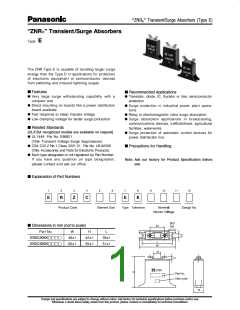
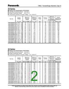
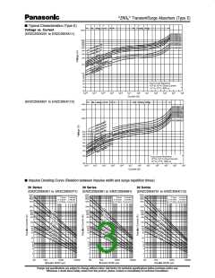
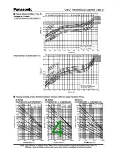
ÒZNRâÓ Transient/Surge Absorbers (Type E)
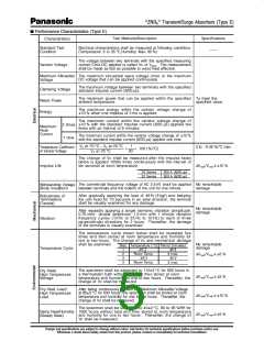
n Performance Characteristics (Type E)
Test Methods/Description
Specifications
ÑÑ
Characteristics
Standard Test
Condition
Electrical characteristics shall be measured at following conditions
(Temperature: 5 to 35 ¡C,Humidity: Max. 85 %)
The voltage between two terminals with the specified measuring
current CmA DC applied is called Vc or VCmA
. The measurement
Varistor Voltage
shall be made as fast as possible to avoid heat affection.
The maximum sinusoidal wave voltage (rms) or the maximum
DC voltage that can be applied continuously.
Maximum Allowable
Voltage
The maximum voltage between two terminals with the specified
standard impulse current (8/20 µs).
Clamping Voltage
Rated Power
Energy
The maximum power that can be applied within the specified To meet the
ambient temperature.
specified value.
The maximum energy within the varistor voltage change of
±10 % when one impulse of 2 ms is applied.
The maximum current within the varistor voltage change of
±10 % with the standard impulse current (8/20 µs) applied two
times with an interval of 5 minutes.
2 times
Maximum
Peak
Current
1 time
The maximum current within the varistor voltage change of ±10 %
with the standard impulse current (8/20 µs) applied one time.
VC at 70 ¡C Ð VC at 20 ¡C
VC at 20 ¡C
1
50
0 to Ð0.05 %/ûC max.
Temperature Coefficient
of Varistor Voltage
´
´ 100 (%/¡C)
The change of Vc shall be measured after the impulse listed
below is applied 10000 times continuously with the interval of
ten seconds at room temperature.
ÆV1mA/V1mA < ±10 %
Impulse Life
20 Series
32 Series
200 A (8/20 µs)
300 A (8/20 µs)
The commercial frequency voltage of AC 2.5 kV shall be applied No remarkable
Withstanding Voltage
(Body Insulation)
between terminals and the bottom of the unit for one minute.
damage
After gradually applying the load of 49 N (5 kgf) and keeping
the unit fixed for 10 seconds in an axial direction, the terminal
shall be visually examined for any damage.
Robustness of
Terminations
(Tensile)
No remarkable
damage
After repeadly applying a single harmonic vibration (amplitude:
0.75 mm): double amplitude: 1.5 mm with 1 minute vibration
frequency cycles (10 Hz to 55 Hz to 10 Hz) to each of three
perpendicular directions for 2 hours. Thereafter, the damage
of the terminals is visually examined.
Vibration
The temperature cycle shown below shall be repeated five
times and then stored at room temperature and humidity for
one to two hours. The change of Vc and mechanical damage
shall be examined.
No remarkable
damage
Step Temperature (ûC) Period (minutes)
Temperature Cycle
0
1
2
3
4
Ð25 Ð3
30+ 3
0
Room Temp.
3 max.
ÆV1mA/V1mA < ±5 %
85+ 3
30+ 3
0
0
Room Temp.
3 max.
The specimen shall be subjected to 110±3 ¡C for 500 hours in
a thermostatic bath without load and then stored at room
temperature and humidity for one to two hours. Thereafter, the
change of Vc shall be measured.
Dry Heat/
High Temperature
Storage
ÆV1mA/V1mA < ±5 %
ÆV1mA/V1mA < ±10 %
ÆV1mA/V1mA < ±5 %
After being continuously applied the Maximum Allowable Voltage
at 85±5 ¡C for 500 hours, the specimen shall be stored at room
temperature and humidity for one to two hours. Thereafter, the
change of Vc shall be measured.
Dry Heat Load/
High Temperature
Load
The specimen shall be subjected to 40±2 ¡C, 90 to 95 %RH for
1000 hours without load and then stored at room temperature
and humidity for one to two hours. Thereafter, the change of
Vc shall be measured.
Damp Heat/Humidity
(Steady State)
$ESIGN AND SPECIlCATIONS ARE SUBJECT TO CHANGE WITHOUT NOTICEꢀ !SK FACTORY FOR TECHNICAL SPECIlCATIONS BEFORE PURCHASE ANDꢁOR USEꢀ
7HENEVER A DOUBT ABOUT SAFETY ARISES FROM THIS PRODUCTꢂ PLEASE CONTACT US IMMEDIATELY FOR TECHNICAL CONSULTATIONꢀ

 PANASONIC [ PANASONIC ]