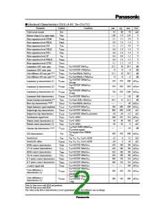
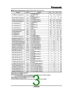
■ Electrical Characteristics (cont.) (V
CC=
4.6V, Ta=25±2˚C)
Parameter
Symbol
Condition
min
510
typ
max
930 mVP–P
dB
Unit
V22=10STEP 500mVP–P
V24=10STEP 1VP–P
10 step
V23=10STEP 500mVP–P
V24=10STEP 1V
VCGAM3
720
Color difference γ characteristics (3)
VGAM4
–2
0
2
Between channels γ characteristics
Color difference gain control characteristics (1)Note B)
Color difference gain control characteristics (2)Note B)
VCGC1
VCGC2
V22=Sin500kHz 600mVP–P
V23=Sin500kHz 600mVP–P
700
700
1150
1150
1500 mVP–P
1500 mVP–P
V5=10STEP 1VP–P
3rd step
V5=10STEP 1VP–P
5 step
V5=10STEP 1VP–P
10 step
VIGAM1
VIGAM2
VIGAM3
220
350
470
300
480
630
390 mVP–P
620 mVP–P
800 mVP–P
Iris γ characteristics (1)
Iris γ characteristics (2)
Iris γ characteristics (3)
VYBLK
VIBLK
VRBLK
VBBLK
V69=C–GND
V5=C–GND
V22=C–GND
V23=C–GND
–20
–20
–20
–20
0
0
0
0
20
20
20
20
mV
mV
mV
mV
Luminance signal blanking level
Iris signal blanking level
R-Y blanking level
B-Y blanking level
V54=10STEP 200mVP–P
V56=10STEP 200mVP–P
VAP generation circuit gain Note C)
VVAP
310
450
610 mVP–P
Edge suppression characteristics (1)Note B)
Edge suppression characteristics (2)Note B)
Luminance high-cut characteristics
AP mix circuit luminance amplification characteristics
VEDGE1
VEDGE2
VHC
V22=Sin500kHz 600mVP–P
V23=Sin500kHz 600mVP–P
V65=10STEP 1500mVP–P
V16=10STEP 300mVP–P
V16=Sin3.5MHz 100mVP–P
V13=Sin3.5MHz 600mVP–P
V11=Sin500kHz 600mVP–P
V13=Sin3.5MHz 600mVP–P
V16=Vref
–20
–20
dB
dB
mV
dB
ns
350
6.9
VAPY
)
Horizontal APDL group delay Note A, D
VAPDL
VAPHAP
VAPVAP
VLLSP
120
3.4
)
Aperture mix circuit HAP gain Note B
dB
dB
dB
mV
)
Aperture mix circuit VAP gain Note B, E
3.3
Aperture suppression characteristics Note B)
–12
515
VWFADE
White fade characteristics
V37=Sin500kHz 500mVP–P
(V38=0.5V)
V42=Sin500kHz 500mVP–P
(V41=0.5V)
V37=Sin500kHz 500mVP–P
(V38=3.0V)
V42=Sin500kHz 500mVP–P
(V41=3.0V)
)
Delay signal amp. gain (1)Note A
VDLAMP1
VDLAMP2
VDLAMP3
VDLAMP4
VCHC
0
0
dB
dB
dB
dB
dB
)
Delay signal amp. gain (2)Note A
)
Delay signal amp. gain (3)Note A
8
)
Delay signal amp. gain (4)Note A
8
V22=V23=Sin500kHz 600mVP–P
(V5=white)
Color difference high-clip characteristics Note B
)
–26
)
Color difference fade characteristics Note B
VCFADE
VSHLPF
VCLPF
V22=V23=Sin500kHz 600mVP–P
V65=Sin3.5MHz 1500mVP–P
V22=V23=Sin3.5MHz 600mVP–P
V48=V50=Sin500kHz 200mVP–P
V48=V50=Sin3.5MHz 200mVP–P
V54=V56=Sin500kHz 500mVP–P
–26
–30
–26
0
dB
dB
dB
dB
dB
dB
)
S/H LPF characteristics Note A
Color difference LPF characteristics Note B
)
)
VAP LPF characteristics (1)Note A
VVLPF1
VVLPF2
VEHPF
)
VAP LPF characteristics (2)Note A
–25
–4
)
Edge HPF characteristics Note A
Note A) Sine waves with BLK and pedestal
Note B) Sine waves with BLK
Note C) For the AN2147FHP, 450mVP-P min., 665mVP-P typ., and 880mVP-P max. under the conditions
V48=10STEP 200mVP-P and V50=10STEP 200mVP-P
Note D) 90ns typ. for the AN2146FHP and the AN2147FHP
Note E) 6.0dB typ. for the AN2147FHP
.
The value in the above characteristics is not a guaranteed value, but reference one on design.

 PANASONIC [ PANASONIC ]