PAM8404
3W/CH Filterless Stereo Class-D Audio Amplifier
Application Information
Gain Settin
For this reason, a low-leakage tantalum or
ceramic capacitor is the best choice. When
The gain of PAM8404 can be selected as 6,12,18
or 24 dB utilizing the G0 and G1 gain setting pins.
The gains showed in the following table are
realized by changing the input resistors inside the
amplifier. The input impedance changes with the
gain setting.
polarized capacitors are used, the positive side of
the capacitor should face the amplifier input in
most applications as the DC level is held at VDD/2,
which is likely higher than the source DC level.
Please note that it is important to confirm the
capacitor polarity in the application.
If the corner frequency is within the audio band,
the capacitors should have a tolerance 10% or
better, because any mismatch in capacitance
cause an impedance mismatch at the corner
frequency and below.
Table-1: Gain Setting
G1 G0 GAIN GAIN INPUT IMPEDANCE
(V/V) (dB)
(kΩ)
28.1
17.3
9.8
0
0
1
1
0
1
0
1
2
4
6
12
18
24
Decoupling Capacitor (CS)
8
The PAM8404 is a high-performance CMOS audio
amplifier that requires adequate power supply
decoupling to ensure the output total harmonic
distortion (THD) as low as possible. Power supply
decoupling also prevents the oscillations causing
by long lead length between the amplifier and the
speaker.
16
5.2
For optimal performance the gain should be set to
2x (Ri=150kΩ). Lower gain allows the PAM8404
to operate at its best, and keeps a high voltage at
the input making the inputs less susceptible to
noise. In addition to these features, lower value of
Gain minimizes pop noise.
The optimum decoupling is achieved by using two
different types of capacitors that target on
different types of noise on the power supply
leads. For higher frequency transients, spikes, or
digital hash on the line, a good low equivalent-
series-resistance (ESR) ceramic capacitor,
typically 1μF, is placed as close as possible to the
device each VDD and PVDD pin for the best
operation. For filtering lower frequency noise
signals, a large ceramic capacitor of 10μF or
greater placed near the audio power amplifier is
recommended.
Input Capacitors (Ci )
In the typical application, an input capacitor, Ci, is
required to allow the amplifier to bias the input
signal to the proper DC level for optimum
operation. In this case, Ci and the input
impedance Ri form a high-pass filter with the
corner frequency determined by the follow
equation:
1
fC =
2pRiCi
(
)
How to Reduce EMI
It is important to consider the value of Ci as it
directly affects the low frequency performance of
the circuit. When Ri is 28.1kΩ and the
specification calls for a flat bass response are
down to 200Hz, the equation is reconfigured as
follows:
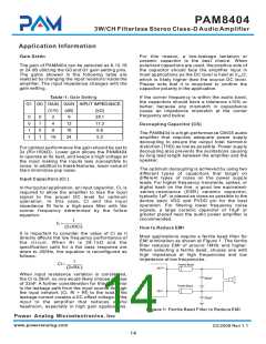
Most applications require a ferrite bead filter for
EMI elimination as shown at Figure 1. The ferrite
filter reduces EMI of around 1MHz and higher.
When selecting a ferrite bead, choose one with
high impedance at high frequencies and low
impedance at low frequencies.
1
Ci =
Ferrite Bead
OUT+
2pR
ifc
(
)
When input resistance variation is considered,
the Ci is 28nF, so one would likely choose a value
of 33nF. A further consideration for this capacitor
is the leakage path from the input source through
the input network (Ci, Ri + Rf) to the load. This
leakage current creates a DC offset voltage at the
input to the amplifier that reduces useful
headroom, especially in high gain applications.
220pF
Ferrite Bead
OUT-
220pF
Figure 1: Ferrite Bead Filter to Reduce EMI
Power Analog Microelectronics,Inc
www.poweranalog.com
03/2009 Rev 1.1
14

 PAM [ POWER ANALOG MICOELECTRONICS ]