TransDimension
TD243
Product Brief
I
I
L
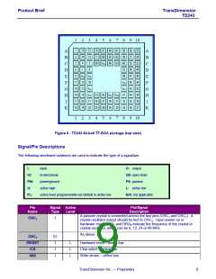
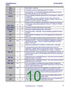
Read strobe – active low.
/RD
7 bit address bus for an addressing space of 512 bytes.
A8:A2
32-bit data bus. D31:D16 should be pulled down with resistors (15K ohm)
but not tied directly to Vss, for 16-bit mode.
IO
IO
D31:D0
This is an output to switch the external 5V for OTG operation (1: VBUS off;
0: VBUS on).
/EXVBO
L
At POR (power-on-reset) or hardware reset the value of this pin will
determine the width of the data bus (1: 32 bits; 0: 16 bits). If the pin is left
floating, 32-bit bus is assumed. See Note 2.
Sensed at POR and hardware reset (/RESET) to determine the frequency
of the crystal or the crystal oscillator (00: 6 MHz; 01: 12 MHz; 10: 24 MHz;
11: 48 MHz).
IO
PL
DRQ1: DRQ0
DACK1, DACK0
EOT1, EOT0
TEST
I
I
I
PL
PL
H
These pins should be pulled up with a 10K resistor.
These pins should be pulled up with a 10K resistor.
Factory test mode – active high. This pin should be grounded for normal
operation.
O
L
When asserted, this indicates to turn on the gang power for all host ports –
active low.
/PO
I
L
Over current condition indicator for gang powered host ports – active low.
/OC
INT
Interrupt to the MCU. This pin can be software configured as a regular or
open drain (OD) output. This pin is software programmable. (OD is the
default). See Note 3.
O/OD
PL
Wakeup the peripheral/OTG controller in suspend mode – active high.
I
I
H
WAKEUP
ID
Connected to the ID pin of the mini-AB connector (Port 1) for OTG
applications. With the help of an internal pull-up resistor, it determines the
chip’s responsibility in an OTG application, (0: A-Device, 1: B-Device).
IO
Data lines for Port 1, which may serve as a host, peripheral or OTG port. If
not used, these two pins can be left floating since the chip has internal pull
down resistors.
DM1, DP1
Data lines for Port 2, a dedicated host port. If not used, each pin should be
pulled down with a 15K resistor.
IO
DM2, DP2
Data lines for Port 3, a dedicated host port. If not used, each pin should be
pulled down with a 15K resistor.
IO
DM3, DP3
PS
A 0.47 µF capacitor is connected across these two pins to support the
internal charge pump circuit. If the internal charge pump is not used, these
two pins may be left unconnected.
CEX1, CEX2
PW
Serving as the A-device in an OTG application, this is the 5V out of the
internal charge pump (when it is enabled), or the external VBus power. It is
the VBus power from the attached DRD (Dual-Role Device) while working
as an OTG B-device. This pin should be left unconnected when Port 1 is
not used for OTG applications.
VBUS
I
This pin is used in an external circuit to provide voltage feedback for the
internal charge pump which generates Vbus.
VFB
VBP
VBus pulsing control. It is only useful when Port 1 is an OTG port for a B-
device, and the internal VBus charge pump is disabled.
O
H
10
TransDimension Inc. — Proprietary

 OXFORD [ OXFORD SEMICONDUCTOR ]